Präsentation herunterladen
Die Präsentation wird geladen. Bitte warten

1
Digital Output Board and Motherboard
Brief description of the DIGOUT-xxxx-PWM-1A/16-yyyy and the Motherboard ISSMB1-4IO

2
DIGOUT + Motherboard Electronic Development
Development by: Ingenieurbüro für Prozeßautomatisierung ifp Dipl.-Inf. Bernd Beisch Internet: Based on: CPU ISS1.2, AMD 486, 100 MHz, Embedded QNX 4.25, Status: Prototype is now manufactured, finished June 2000

4
Mother-Board Schematics
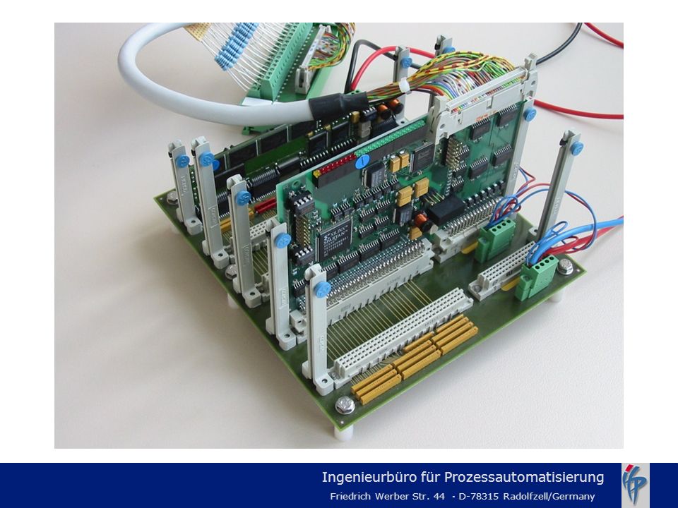
Power 2*5..35 V (switched to actuators, 1 line for 8 relays) Power Supply (7-35V, for Electronic) CPU Board ISS1.2 (486 MHz, 100 MHz) - 2 Ethernet Ports - 1 RS422 Port (Service) 4 IO-Boards (ISA) 200*180 mm
 Power Supply (7-35V, for Electronic) CPU Board ISS1.2. (486 MHz, 100 MHz) - 2 Ethernet Ports. - 1 RS422 Port. (Service) 4 IO-Boards. (ISA) 200*180 mm.")
5
Mother - Board

6
Mother - Board

7
DIGOUT - Board - Overview
16 bit ISA-bus-board 16 digital outputs (High-Side Power Switching) Each digital output has its own PWM (Pulse Width Modulation) The basis board can be individually adapted for various applications via piggy packs via firmware updates (per download to SE²PROM (serial E²PROM)) via download from internet
 Each digital output has its own PWM (Pulse Width Modulation) The basis board can be individually adapted for various applications. via piggy packs. via firmware updates (per download to SE²PROM (serial E²PROM)) via download from internet.")
8
DigOut Board

9
DIGOUT - Board Schematics
100 mm 160 mm

10
DIGOUT - Board Characteristics I
Operating temperature Dimension FPGA Firmware storage (SE²PROM) On/off status display Error status display ESD protection Power connector interfaces In Out °C 100 mm * 160 mm 10000 systems gate XILINX 256 KBit One green LED for each output One red LED together for two output 0,5 KV 32 pin VG connector, max. 1 A/pin, 5V .. 34V 40 pin Harting, max. 1 A/pin
 On/off status display. Error status display. ESD protection. Power connector interfaces. In. Out °C. 100 mm * 160 mm systems gate XILINX. 256 KBit. One green LED for each output. One red LED together for two output. 0,5 KV. 32 pin VG connector, max. 1 A/pin, 5V .. 34V. 40 pin Harting, max. 1 A/pin.")
11
DIGOUT - Board Characteristics II
Bus interface Power supply for onboard electronic Piggy pack interface 16 bit ISA-bus via 96 pin VG connector 5V and 24V via 96 pin VG connector 8 bidirect connections to FPGA 8 bidirect connections to power connector interface OUT

12
High-Side Power Switch Characteristics (Power Connector OUT)
Nominal load current Operating voltage Overvoltage protection Overload protection (auto shutdown) Short-circuit protection Current limitation Undervoltage shutdown Overvoltage shutdown Turn on time to 90 % Vout Turn off time to 10 % Vout 1 A V 43 V 150 °C (chip temperature) 4 A 5 V V Typ. 200 µs
 Short-circuit protection. Current limitation. Undervoltage shutdown. Overvoltage shutdown. Turn on time to 90 % Vout. Turn off time to 10 % Vout. 1 A V. 43 V. 150 °C (chip temperature) 4 A. 5 V V. Typ. 200 µs.")
13
Pulse Width Modulator PWM Characteristics
basis frequency register duty cycle registers (for each output) resolution of duty cycle 16 bit, 4 Hz..1kHz 16 bit 1 bit 3,8 µs Duty Cycle Resolution: 100% = 6758 control steps 0.2 ms (0.8%) X % 25 ms (40 Hz) 100 %
 resolution of duty cycle. 16 bit, 4 Hz..1kHz. 16 bit. 1 bit 3,8 µs. Duty Cycle. Resolution: 100% = 6758 control steps. 0.2 ms (0.8%) X % 25 ms (40 Hz) 100 %")
14
Block Diagram DIGOUT - Board

15
DIGOUT - Board Block Diagram of two Channels of High-Side Power Switch BTS 711 L1

16
DIGOUT - Board Status Display

17
Example - Piggy Pack (AquaPro)
For AquaPro: measure the quantity of fluid flowing through a counting flow meter Alternate possibilities (in discussion): get analog/digital feedback signals feedback actuator actual signals detect zero-voltage-transition points and thereby enable a phase control circuit ...
: get analog/digital feedback signals. feedback actuator actual signals. detect zero-voltage-transition points and thereby enable a phase control circuit. ...")
18
Flow Measurement Piggy Pack Characteristics
Sensor connector Electrical characteristic to sensor Value register via FPGA Status display Dimension 3 pin, via Power Connector Out 24 V, open collector 100 mA 16 bit; update frequency min. 4 Hz One green LED (frequency input OK) 100 mm * 80 mm Designed for Flowmeter KOBOLD DF* (or similar) i.e. DF-24: - 24 l/min = 1440 l/h - 233 Impulse/l - 93 Hz = 100% flow
 100 mm * 80 mm. Designed for Flowmeter KOBOLD DF* (or similar) i.e. DF-24: - 24 l/min = 1440 l/h Impulse/l Hz = 100% flow.")
Ähnliche Präsentationen


![Z-Transformation Die bilaterale Z-Transformation eines Signals x[n] ist die formale Reihe X(z): wobei n alle ganzen Zahlen durchläuft und z, im Allgemeinen,](/1/205073/big_thumb.jpg "Z-Transformation Die bilaterale Z-Transformation eines Signals x[n] ist die formale Reihe X(z): wobei n alle ganzen Zahlen durchläuft und z, im Allgemeinen,>")


