Präsentation herunterladen
Die Präsentation wird geladen. Bitte warten

1
17 x 16 Hydraulik Einführung
Closed Centre Load Sensing hydraulic system All 16/17 x 16 units are fitted with CCLS hydraulic system - Open centre hydraulic system is not an option with these transmissions Closed centre load sensing type hydraulic pump Electronic Draft Control ( EDC ) lift Mechanical Draft Control (MDC) lift Bosch remote valves
 lift. Mechanical Draft Control (MDC) lift. Bosch remote valves.")
2
High Pressure Circuit Components and Pipework

3
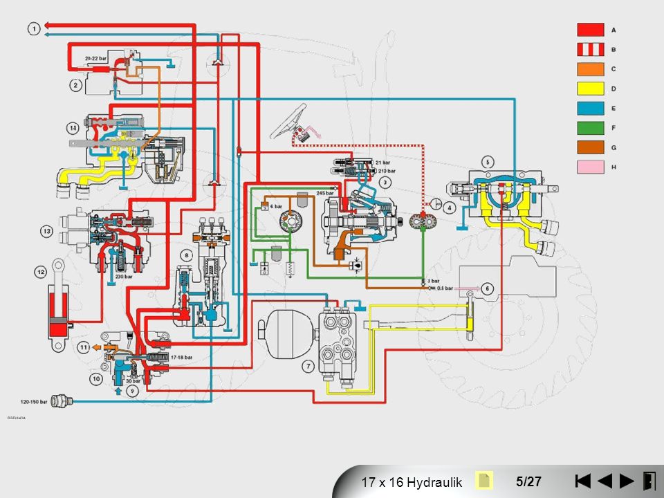
PROFI 17 x 16 Hydrauliksystem Schema
Kriechgang PROFI 17 x 16 Hydrauliksystem Schema 4WD Differentialsperren PTO Kupplung / Bremse Kupplung C1/C2/C3/C4/C5 EHR Vorsteuer- druckregelventil Synchronschltung V/R,4/5 10 bar Terraglide VA-Federung Gtriebeschmierung PTO-Schmierung Pumpenrad- Schmierung Differential-Schmierung C5-Schmierung 22 bar Mittelanbau ventile 30 bar Sicherheisventil EHR-Ventile 1-4 P1 Systemdruck- ventil 16/18 bar EDC-Ventil Power Beyond Anhänger- bremsventil bar 7 bar 245 bar Sicherheitsventil CCLS 113 l/m Standby 24 ± 1 bar Max. 210 ± 5 bar 186 bar 3 bar Ladedruck- begrenzungs- ventil Lenkservostat Ölkühler 6 bar Druckfilter 22-28 l/m 6 bar Druckfilter- begrenzungs ventil 125 l/m 40 l/m Lade- pumpe Lenkungspumpe 0.8 bar Saugfilter

4
Oil flows Vacuum oil - Green Charge pressure oil - Brown High pressure system oil - Red Components Output from piston pump ( 1 ) Intake filter restriction switch ( 2 ) Charge pump ( 3 ) Low charge pressure switch ( 4 ) Charge pressure by-pass valve ( 5 ) Steering pump ( 6 ) Charge pressure filter dump valve ( 7 ) Not available in the Repair Manual
 Intake filter restriction switch ( 2 ) Charge pump ( 3 ) Low charge pressure switch ( 4 ) Charge pressure by-pass valve ( 5 ) Steering pump ( 6 ) Charge pressure filter dump valve ( 7 ) Not available in the Repair Manual.")
6
16 x16 low pressure circuit 1. Steering motor 2. Cooler bypass valve 3. Lub valve 4. Transmission side plate ( feeds the 4 hydraulic clutches) 5. Pump 6. Steering pump 7. Priority valve 8. PTO brake 9. PTO 10. Low pressure distribution block 11. Diff 12. 4WD 13. Transmission top plate ( feeds F/R & 1-4/5-8 synro’s)
")
7
Oil Flow in Raising Spool moved to the left (raise) via pilot line oil from the solenoid control unit, supplied from Gallery ‘I’. Moving the spool to the raise position causes the pin (10) on the lock valve to ride up the ramp of the spool and hold the valve in the open position. Gallery ‘B’ is now open to gallery ‘C’ and Gallery ‘E’ is open to gallery ‘F’. The flow from gallery ‘C’ is blocked by the load hold check valve ball (3) until pressure in the gallery is sufficient to lift the ball off its seat against the back pressure in the lift port gallery ‘E’. Oil can flow from: Gallery ‘C’ past the load hold check valve into Gallery ‘E’. Across the flat on the main control spool to Gallery ‘F’. Through the lock valve (11) Out through the raise port (12) of the RV. Exhaust oil from the extending cylinder returns through the lowering port and gallery (H), around the land on the main control spool and back to reservoir via the common gallery ‘G’. If the load hold check valve (3) was not installed the situation could occur where pump pressure is insufficient to support the load in the raise port when the RV is moved from neutral to raise condition. Under this situation the load would momentarily drop until pump pressure was sufficient to support the load. The rate of flow through the RCV is controlled electronically by the control unit solenoid, again based on the setting of the flow potentiometer within the cab. To maintain set flow through the remotes under all conditions with varying pump inlet pressure in parallel gallery ‘A’ the flow control spool senses the pressure and the spool adjusts to provide the required flow at each operating remote. The differential pressure sensed on each end of the spool causes the spool to move to a new state of equilibrium and continually regulates the flow across the spool metering lands (2) to maintain a constant flow through the flow control restriction irrespective of pressure in other hydraulic circuits. The pressure in gallery ‘C’ is also transmitted down the load sensing gallery ‘D’ to the flow compensating valve of the variable flow piston pump where pump output is regulated according to circuit demand.
 on the lock valve to ride up the ramp of the spool and hold the valve in the open position. Gallery ‘B’ is now open to gallery ‘C’ and Gallery ‘E’ is open to gallery ‘F’. The flow from gallery ‘C’ is blocked by the load hold check valve ball (3) until pressure in the gallery is sufficient to lift the ball off its seat against the back pressure in the lift port gallery ‘E’. Oil can flow from: Gallery ‘C’ past the load hold check valve into Gallery ‘E’. Across the flat on the main control spool to Gallery ‘F’. Through the lock valve (11) Out through the raise port (12) of the RV. Exhaust oil from the extending cylinder returns through the lowering port and gallery (H), around the land on the main control spool and back to reservoir via the common gallery ‘G’. If the load hold check valve (3) was not installed the situation could occur where pump pressure is insufficient to support the load in the raise port when the RV is moved from neutral to raise condition. Under this situation the load would momentarily drop until pump pressure was sufficient to support the load. The rate of flow through the RCV is controlled electronically by the control unit solenoid, again based on the setting of the flow potentiometer within the cab. To maintain set flow through the remotes under all conditions with varying pump inlet pressure in parallel gallery ‘A’ the flow control spool senses the pressure and the spool adjusts to provide the required flow at each operating remote. The differential pressure sensed on each end of the spool causes the spool to move to a new state of equilibrium and continually regulates the flow across the spool metering lands (2) to maintain a constant flow through the flow control restriction irrespective of pressure in other hydraulic circuits. The pressure in gallery ‘C’ is also transmitted down the load sensing gallery ‘D’ to the flow compensating valve of the variable flow piston pump where pump output is regulated according to circuit demand.")
8
Oil Flow in Lowering Spool moved to the right (lowering) via pilot line oil from the solenoid control unit, supplied from Gallery ‘I’. The position of the spool causes the pin on the lock valve to hold the valve in the open position Gallery ‘B’ is now open to gallery ‘C’ and gallery ‘E’ is open to gallery ‘H’. Oil from the parallel gallery ‘A’ flows past the flow control valve spool and restrictor (2) into gallery ‘C’ and the load sensing gallery ‘D’. The load hold check valve ball (3) remains closed until pump system pressure is sufficient to overcome the back pressure in gallery ‘E’. When the load hold check valve ball lifts of the seat oil flows into gallery ‘H’, round the control valve spool to gallery ‘G’ and out through the lowering port of the RV coupling. Exhaust oil from the retracting cylinder returns to reservoir gallery ‘G’ through the raising port and lock valve (11). Pump output and system pressure will continually react to the maximum demand of the tractor high pressure hydraulic circuits as sensed through the load sensing lines. Flow through the remotes is controlled in exactly the same manner as described in the ‘Oil Flow in Raising’-slide by sensing differential pressure across the flow control spool.
 into gallery ‘C’ and the load sensing gallery ‘D’. The load hold check valve ball (3) remains closed until pump system pressure is sufficient to overcome the back pressure in gallery ‘E’. When the load hold check valve ball lifts of the seat oil flows into gallery ‘H’, round the control valve spool to gallery ‘G’ and out through the lowering port of the RV coupling. Exhaust oil from the retracting cylinder returns to reservoir gallery ‘G’ through the raising port and lock valve (11). Pump output and system pressure will continually react to the maximum demand of the tractor high pressure hydraulic circuits as sensed through the load sensing lines. Flow through the remotes is controlled in exactly the same manner as described in the ‘Oil Flow in Raising’-slide by sensing differential pressure across the flow control spool.")
9
Oil Flow in Float The float position allows the free flow of oil from both the raise and lower ports of the RV permitting the cilinder to extend or retract freely. When the RV operater control switch is moved to the float position the control spool is moved fully to the right via pilot line oil from the solenoid control unit, supplied from gallery ‘I’. Oil from the gallery ‘B’ to the raise and lower ports is blocked by the land of the spool end. The position of the spool causes pin (7) on the lock valve to hold the valve in the open position. The raise and lower ports of the RV are open to reservoir gallery ‘G’ allowing a free flow of oil from one port of the cylinder to the other. Should a void occur in the circuit oil will be drawn by suction from one side of the cylinder to the other. Click to play
 on the lock valve to hold the valve in the open position. The raise and lower ports of the RV are open to reservoir gallery ‘G’ allowing a free flow of oil from one port of the cylinder to the other. Should a void occur in the circuit oil will be drawn by suction from one side of the cylinder to the other. Click to play.")
10
Operating a Single Remote Valve
Remote Valve in Operation Parallel Gallery (Interconnecting Remote Valves Sections) Load Sense Line (Interconnecting Remote Valves Sections) B. Remote Valves in Neutral 3. Spool Metering Lands 4. Flow Control Spool 5. Load Sense Line Check Valve Remotes and EDC have common supply gallery ( 1 ) and individual flow control valves ( 4 ). If no flow control valve, then oil would flow to lowest pressure system. High pressure / Neutral When one remote is operating, pressure in load sense line ( 2 ) equals operating pressure of remote valve. Flow through the electro-hydraulic RV is set by turning the operator controlled potentiometer in the cab. The flow is then determined by the control valve spool which is electrically controlled by the control unit solenoid. The pressure differential in combination with the spring acting on the ends of the flow control spool causes the spool to move to a position of equilibrium which adjusts the flow across the spool metering lands (3). The adjustment of flow across the metering land (3) produces a constant flow through the remote valve.
 Load Sense Line (Interconnecting Remote Valves Sections) B. Remote Valves in Neutral. 3. Spool Metering Lands. 4. Flow Control Spool. 5. Load Sense Line Check Valve. Remotes and EDC have common supply gallery ( 1 ) and individual flow control valves ( 4 ). If no flow control valve, then oil would flow to lowest pressure system. High pressure / Neutral. When one remote is operating, pressure in load sense line ( 2 ) equals operating pressure of remote valve. Flow through the electro-hydraulic RV is set by turning the operator controlled potentiometer in the cab. The flow is then determined by the control valve spool which is electrically controlled by the control unit solenoid. The pressure differential in combination with the spring acting on the ends of the flow control spool causes the spool to move to a position of equilibrium which adjusts the flow across the spool metering lands (3). The adjustment of flow across the metering land (3) produces a constant flow through the remote valve.")
Ähnliche Präsentationen


 Kapitel 8 P-R Kap. 7>")


