Präsentation herunterladen
Die Präsentation wird geladen. Bitte warten

1
CMS TRIGGER J. Erö, M. Fierro, A. Jeitler, N. Neumeister, P. Porth, H. Rohringer, L. Rurua, H. Sakulin, A. Taurok, C.-E. Wulz; H. Bergauer, C. Deldicque, K. Kastner, M. Padrta (Techniker); L. Boldizsar (temporär) Vorstandssitzung Wien, 29. April 2002
; L. Boldizsar (temporär) Vorstandssitzung Wien, 29. April")
2
Vorstandssitzung, April 2002 Claudia-Elisabeth Wulz2 Triggeraktivitäten Globaler Trigger Globaler Müontrigger Regionaler Müontrigger (DTTF und ) Trigger Control System Softwareentwicklung ORCA Triggerstudien Arbeiten in PRS Müongruppe Apr. 2002: CPT Week

3
Vorstandssitzung, April 2002 Claudia-Elisabeth Wulz3 Board Layout of the Global Trigger Processor PSB (Pipeline Synchronizing Buffer)Input synchronization (7 boards including GMT) GTL (Global Trigger Logic) Logic calculation (1-2 boards) FDL (Final Decision Logic) L1A decision (1 board) TCS (Trigger Control System Module)Trigger Control (1 board) NEW: L1A (Level-1 Accept Module)Delivery of L1A (1 board) TIM (Timing Board)Timing (1 board) GTFE (Global Trigger Frontend) Readout (1 board) A. Taurok, C.-E. Wulz M. Padrta, H. Bergauer, K. Kastner

4
Vorstandssitzung, April 2002 Claudia-Elisabeth Wulz4 New layout of Global Trigger 9U Crate

5
Vorstandssitzung, April 2002 Claudia-Elisabeth Wulz5 Main Global Trigger Rack

6
Vorstandssitzung, April 2002 Claudia-Elisabeth Wulz6 GTL-6U Automatic chip design and setup procedure developed. Layout for a 20 channel GTL (4, 4 isol. e/, 4 central jets, 4 fwd jets, E T, E T miss, 8 jet multiplicities; other quadruplets can be connected alternatively for tests) is currently being finished. 1020-pin Altera FPGA 20k400E not yet included. The layout of a conversion board to be used later in final 9U-crate is ready. It contains also memories in FPGAs to send simulated test data to the GTL-6U board. A decision on a possible redefinition of jet input groups has been taken. It was decided to keep the present best 4 central jets, 4 forward jets and 4 -jets and jet multiplicities for different E T thresholds. A new quantity H T giving the transverse energy sum of all good jets above threshold has been added. The exact definition of how to calculate the jet multiplicities ( -range) still has to be taken at the level of the calorimeter trigger. More than 8 values could be necessary.
 is currently being finished pin Altera FPGA 20k400E not yet included. The layout of a conversion board to be used later in final 9U-crate is ready. It contains also memories in FPGAs to send simulated test data to the GTL-6U board. A decision on a possible redefinition of jet input groups has been taken. It was decided to keep the present best 4 central jets, 4 forward jets and 4 -jets and jet multiplicities for different E T thresholds. A new quantity H T giving the transverse energy sum of all good jets above threshold has been added. The exact definition of how to calculate the jet multiplicities ( -range) still has to be taken at the level of the calorimeter trigger. More than 8 values could be necessary..")
7
Vorstandssitzung, April 2002 Claudia-Elisabeth Wulz7 GTL-9U New: H T

8
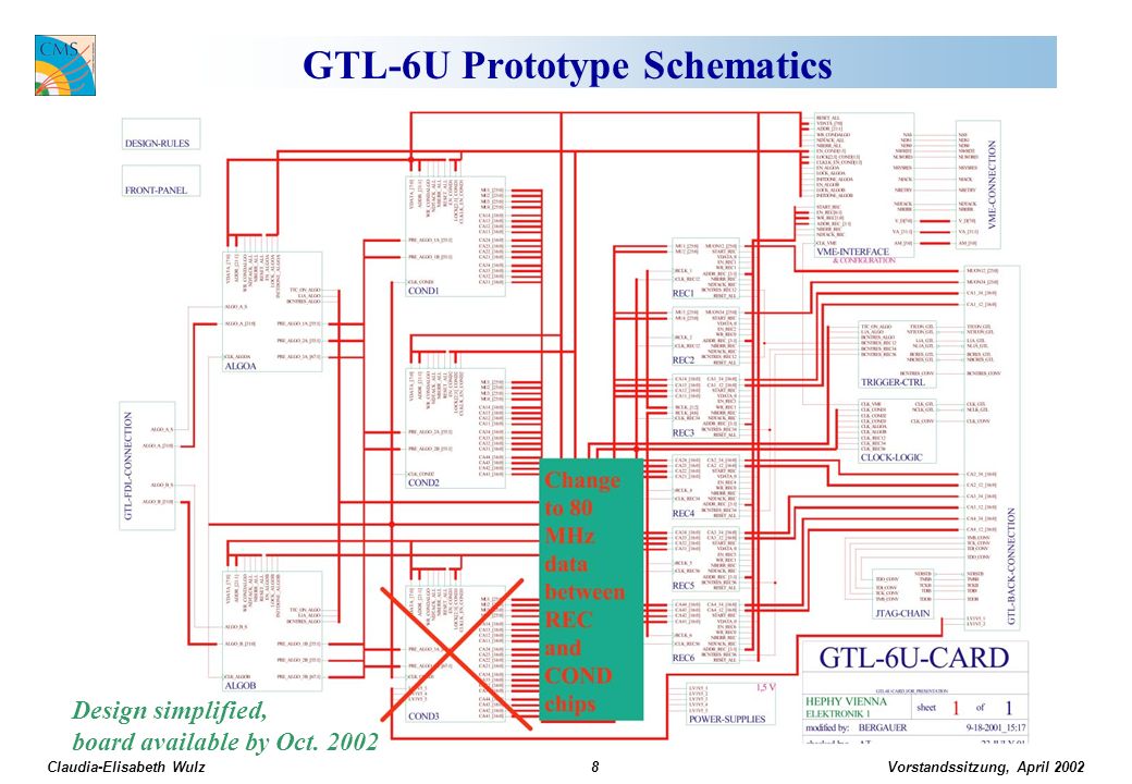
Vorstandssitzung, April 2002 Claudia-Elisabeth Wulz8 GTL-6U Prototype Schematics Design simplified, board available by Oct. 2002
9
Vorstandssitzung, April 2002 Claudia-Elisabeth Wulz9 FDL-9U Schematic and chip design in progress. Board available by Oct. 2002. Monitoring of all algorithm and L1A bits Prescaling of all algorithms Trigger Mask 8 L1As in parallel for partition modes Input of up to 64 technical trigger bits from PSB possible

10
Vorstandssitzung, April 2002 Claudia-Elisabeth Wulz10 TIM-6U TIM-6U: The board contains a TTCrx chip and provides all timing signals for the GT crate. It will also be used in the Drift Tube Track Finder crates. An FPGA provides all necessary test functions to run the crate without the central TTC clock. It simulates also L1A requests for monitoring or to test the readout chain. The schematic design is finished. The layout is on hold until May 2002 due to TTCrx jitter problems. We would prefer to keep the TTCrx as a mezzanine board with interconnections identical to current board. The final Timing Board will be 6U (previously 9U).
..")
11
Vorstandssitzung, April 2002 Claudia-Elisabeth Wulz11 TIM-6U

12
Vorstandssitzung, April 2002 Claudia-Elisabeth Wulz12 TCS-9U TCS-9U: The main functions are defined but the design is still open for additional requests (calibration logic etc.). The board is expected by Oct. 2002. Trigger Partitions: The maximum number of subsystems is fixed (32). A preliminary agreement about the output to the DAQ Event Manager has been reached. The input format of Fast Signals is now fixed. 4 coded bits per subsystem, sent as LVDS parallel data, and RJ45 connectors are proposed. The TCS board provides data for the new CMS-TTCvi. A L1A driver module to be used with the CMS-TTCvi has been conceived.
. A preliminary agreement about the output to the DAQ Event Manager has been reached. The input format of Fast Signals is now fixed. 4 coded bits per subsystem, sent as LVDS parallel data, and RJ45 connectors are proposed. The TCS board provides data for the new CMS-TTCvi. A L1A driver module to be used with the CMS-TTCvi has been conceived..")
13
Vorstandssitzung, April 2002 Claudia-Elisabeth Wulz13 TCS-9U environment

14
Vorstandssitzung, April 2002 Claudia-Elisabeth Wulz14 Global Trigger Milestones 2002 Milestone March 2002: System Test -> Delayed to Oct. 2002 This includes the backplane, the PSB-6U, GTL-6U, FDL-9U and TIM-6U. The GTFE and the GMT are not included. Milestone July 2002: TCS-6U tested -> Delayed to Oct. 2002 Milestone Oct. 2002: Backplane-9U tested -> OK

15
Vorstandssitzung, April 2002 Claudia-Elisabeth Wulz15 Global Trigger Milestones beyond 2002 Milestone June 2003: Complete GT prototype available Integration tests possible from this date. GTFE-9U: Conceptual design of readout board done. Milestone July 2004: 12-channel PSB-9U available PSB-9U: Conceptual design done. Will have memories inside FPGAs. Milestone Nov. 2004: Complete GT available Includes GTL-9U module with all input channels (4, 4 isol. e/, 4 non-isol. e/, 12 jet channels, H T, E T, E T miss, jet multiplicities). The Global Muon Trigger will have been completed by Nov. 2003.
. The Global Muon Trigger will have been completed by Nov")
16
Vorstandssitzung, April 2002 Claudia-Elisabeth Wulz16 Barrel-Endcap Overlap Region Notwendig für hohe Effizienz: Verwendung von MB2/1 Segmenten im CSC TF Verwendung von ME1/3 Segmenten im DT TF Ghosting (Duplikation) entsteht, wenn … DT und CSC Trigger das selbe Muon finden dasselbe Muon einmal im Barrel (z.B. DT) und einmal im Endcap (z.B. forward-RPC) gefunden wird problematisch für Di-Muon-Trigger Szenarien zur Verhinderung von Duplikation wurden untersucht Auf Ebene der DT und CSC Trigger Track Finder Optimierung der Zuordnung von Segmenten in ME1/3 zu DT und CSC Trigger Cancel-Out Schema mit 1 Tag-Bit pro CSC-Segment in ME1/3 Cancel-Out Schema mit 1 Tag Bit pro DT-Segment in MB2/1 Auf Ebene des Global Muon Triggers Bestätigung von DT/CSC Muonen durch RPC DT/CSC Cancel-Out Hardware Unit MB2/1 ME1/3 H. Sakulin
 und einmal im Endcap (z.B. forward-RPC) gefunden wird problematisch für Di-Muon-Trigger Szenarien zur Verhinderung von Duplikation wurden untersucht Auf Ebene der DT und CSC Trigger Track Finder Optimierung der Zuordnung von Segmenten in ME1/3 zu DT und CSC Trigger Cancel-Out Schema mit 1 Tag-Bit pro CSC-Segment in ME1/3 Cancel-Out Schema mit 1 Tag Bit pro DT-Segment in MB2/1 Auf Ebene des Global Muon Triggers Bestätigung von DT/CSC Muonen durch RPC DT/CSC Cancel-Out Hardware Unit MB2/1 ME1/3 H. Sakulin.")
17
Vorstandssitzung, April 2002 Claudia-Elisabeth Wulz17 Effizienz und Ghosts mit verschiedenen Szenarien DT/CSC Cancel-Out Hardware Unit im Global Muon Trigger ist notwendig –inkludiert in GMT Hardwaredesign –inkludiert in ORCA-Simulation CMS Internal Notes –CMS Internal Note 2002/024, H. Sakulin, A Robust Solution to the Ghosting Problems of the CMS L1 Trigger in the Barrel/Endcap Overlap Region –CMS Internal Note (in preparation), D. Acosta et al., Specification of the Interface between DT and CSC Level-1 Track Finders (*) Effizienz und Ghosts in der Overlap Region 0.9 < | | < 1.2 Barrel-Endcap Overlap Region 0.42 % 92.5 %GMT: Cancel Out Hardware Unit 0.04 % 88.3 %GMT: Bestätigung durch RPC 2.22 %91.7 %Cancel-Out nur auf Track-Finder Level (bestes Szenario) Ghosts (*) Effizienz (*) Szenario
, D. Acosta et al., Specification of the Interface between DT and CSC Level-1 Track Finders (*) Effizienz und Ghosts in der Overlap Region 0.9 < | | < 1.2 Barrel-Endcap Overlap Region 0.42 % 92.5 %GMT: Cancel Out Hardware Unit 0.04 % 88.3 %GMT: Bestätigung durch RPC 2.22 %91.7 %Cancel-Out nur auf Track-Finder Level (bestes Szenario) Ghosts (*) Effizienz (*) Szenario.")
18
Vorstandssitzung, April 2002 Claudia-Elisabeth Wulz18 Neue Methode zur Behandlung von Pile - up in der Simulation pt1 pt4 pt10 CMSIM oohitfz digi PU oohitfz oohitfz trig ORCA jobs grosses Sample von Bunch Crossings modifiziertes ORCA: einzelne Interaktionen werden ueberlagert Interaktionen mit Muonen, bins in muon-p T MIX Pile-Up ohne Muonen Überlagerung vonverschiedenen Interaktionen(mit Muonen)im selben Bunch Crossingwird korrekt simuliert Ambestenmöglich inder ORCA-Digitalisierung Modifikation von ORCAerforderlich Sollfür 2002 Muon-Monte-Carlo-Produktion verwendet werden CMS Internal Note (in Vorbereitung): H. Sakulin:, Obtaining single- and di- muon trigger rates from monte-carlo samples

19
Vorstandssitzung, April 2002 Claudia-Elisabeth Wulz19 Drift Tube Trigger Track Finder DTTF-Sektorprozessorkarte - wurde mit der ganzen Funktionalität simuliert (Input Receiver Module inbegriffen) - vollständig in Behavioral VHDL - generell funktionell mit Chip-VHDL-Modellen - Schaltung wurde entwickelt und zur Layout-Entwicklung an CERN weitergeschickt - Bauteile bestellt - Automatische Erzeugung der Lookup-Tables (M. Fierro) Track Finder - VHDL Modell weiterentwickelt und die Verknüpfungen ausgebaut - Testbench mit Ein- und Ausgangsmodulen ergänzt, welche getestet wurden - Board-level Funktionalitätstests mit VHDL Modell durchgeführt (Synchronisationsprobleme nicht vollständig beseitigt) Interface-Fragen gelöst... - Interface zwischen lokaler Triggerelektronik für (Padova/Bologna) - Interface zwischen lokaler Triggerelektronik für (Bologna) J. Erö, Ch. Deldicque
 Track Finder - VHDL Modell weiterentwickelt und die Verknüpfungen ausgebaut - Testbench mit Ein- und Ausgangsmodulen ergänzt, welche getestet wurden - Board-level Funktionalitätstests mit VHDL Modell durchgeführt (Synchronisationsprobleme nicht vollständig beseitigt) Interface-Fragen gelöst... - Interface zwischen lokaler Triggerelektronik für (Padova/Bologna) - Interface zwischen lokaler Triggerelektronik für (Bologna) J. Erö, Ch. Deldicque.")
20
Vorstandssitzung, April 2002 Claudia-Elisabeth Wulz20 Track Finder Software Implementierung des Track Finders in ORCA Entwicklung von stand-alone Software zur Erzeungung der Look-up Tables Erzeugung von neuen Look-up Tables N. Neumeister

21
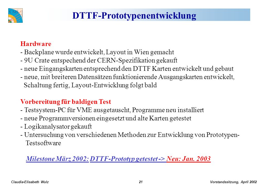
Vorstandssitzung, April 2002 Claudia-Elisabeth Wulz21 DTTF-Prototypenentwicklung Hardware - Backplane wurde entwickelt, Layout in Wien gemacht - 9U Crate entspechend der CERN-Spezifikation gekauft - neue Eingangskarten entsprechend den DTTF Karten entwickelt und gebaut - neue, mit breiteren Datensätzen funktionierende Ausgangskarten entwickelt, Schaltung fertig, Layout-Entwicklung folgt bald Vorbereitung für baldigen Test - Testsystem-PC für VME ausgetauscht, Programme neu installiert - neue Programmversionen eingesetzt und alte Karten getestet - Logikanalysator gekauft - Untersuchung von verschiedenen Methoden zur Entwicklung von Prototypen- Testsoftware Milestone März 2002: DTTF-Prototyp getestet -> Neu: Jan. 2003
22
Vorstandssitzung, April 2002 Claudia-Elisabeth Wulz22 DTTF Test Setup

23
Vorstandssitzung, April 2002 Claudia-Elisabeth Wulz23 Karten für Test Setup J. Erö, Ch. Deldicque

24
Vorstandssitzung, April 2002 Claudia-Elisabeth Wulz24 Global Trigger ORCA Simulation The L1 Global Trigger System is simulated by an ORCA package (starting from ORCA version 5) –Trigger/L1GlobalTrigger Hardware system features are simulated –…except Delta conditions (topological correlations among different classes of trigger objects) and new H T /jet counts Persistency of trigger objects is provided Official documentation is available on the usual ORCA Software description pages M. Fierro

25
Vorstandssitzung, April 2002 Claudia-Elisabeth Wulz25 Implementing an algorithm: syntax Each algorithm is made up of particle blocks of different kind: –MU, EL, IE, CJ, FJ, TJ, ET, EM, JN Each block is numbered to have a one-to-one connection with its own condition settings (up to 64 different blocks per particle can be set): –MU_00, EL_01, FJ_01, EM_63,... An algorithm is a combination of particle blocks, connected by.AND. ( & ),.OR. ( | ) conditions: MU_00&EM_00 | EL_00&EM_00
,.OR. ( | ) conditions: MU_00&EM_00 | EL_00&EM_00.")
26
Vorstandssitzung, April 2002 Claudia-Elisabeth Wulz26 Implementing an algorithm: syntax User can provide algorithms in three different ways: –Use the default implemented algorithms –Write a file named trigger_menu.dat One algorithm per line Blank line allowed This overrides the default Trigger Menu algorithms –Add one algorithm to the default Via adding a line in the.orcarc file L1GlobalTrigger:Algorithm MU_00&EM_00|EL_00&EM_00

27
Vorstandssitzung, April 2002 Claudia-Elisabeth Wulz27 Implementing an algorithm: thresholds For each particle block, user must provide a list of conditions by the WriteThreshold utility It is an interactive tool that writes a file for each specified block Users are asked for which block they want to provide conditions and then they are asked to specify the conditions themselves User can modify conditions for the default implemented algorithms If WriteThreshold is not invoked for a certain block, the conditions for that specific block are set to the default values (now defaults are set to dont care values)
")
28
Vorstandssitzung, April 2002 Claudia-Elisabeth Wulz28 L1GlobalTrigger output The output of L1GT is the Level 1 Trigger Accept word, a string of 128 bits. Each bit corresponds to the output of one algorithm. User can select whether to check the overall L1 accept signal or a specific algorithm bit

29
Vorstandssitzung, April 2002 Claudia-Elisabeth Wulz29 Persistency The information for each trigger object is saved per event, in form of BitArray –24 bit for each muon candidate typedef BitArray(24) MuonDataWord –32 bit for each calorimeter object (req. from L1Calo Group) Actually in the code only 21 bit words are used, following the hardware specifications typedef BitArray(21) CaloDataWord L1Accept word is saved as well BitArray(128)
 Actually in the code only 21 bit words are used, following the hardware specifications typedef BitArray(21) CaloDataWord L1Accept word is saved as well BitArray(128).")
30
Vorstandssitzung, April 2002 Claudia-Elisabeth Wulz30 Persistency User code can access the particle information via L1GlobalTrigger methods: –CaloDataWord getElectrons(int i) –MuonDataWord getMuons(int i) Methods are provided to convert BitArray information into usual particle parameters (E T, p T,,…) The L1GlobalTrigger code itself can run on the database, updating it according to whether the user modified particle conditions/algorithm definitions
 –MuonDataWord getMuons(int i) Methods are provided to convert BitArray information into usual particle parameters (E T, p T,,…) The L1GlobalTrigger code itself can run on the database, updating it according to whether the user modified particle conditions/algorithm definitions")
31
Vorstandssitzung, April 2002 Claudia-Elisabeth Wulz31 L1 GT Efficiency Studies for some Physics Channels The samples for 4 channels have been: generated with PYTHIA 6.136 (1000 events per channel) simulated with CMSIM121 Hit-formatted and digitized with ORCA_5_3_2 Pile-up for high luminosity has been added The samples have then been processed with L1GlobalTrigger The thresholds for calculation of efficiencies of individual algorithms are taken as for calculation of muon, calo and combined rates by M. Fierro and P. Chumney for 4 different DAQ scenarios: 75 kHz, 50 kHz, 37.5 kHz, 25 kHz. L. Boldizsar, A. Jeitler, N. Neumeister, P. Porth, L. Rurua, H. Rohringer, C.-E. Wulz

32
Vorstandssitzung, April 2002 Claudia-Elisabeth Wulz32 Samples used for current analysis H250: H SM WW (leptonic decay) M H = 250 GeV/c 2 H SM WW jj (semileptonic decay) H800: H SM WW (leptonic decay) M H = 800 GeV/c 2 H SM WW jj (semileptonic decay) SUSY1: + E t miss. + jets TTH150: +E t miss. + jets + -jet

33
Vorstandssitzung, April 2002 Claudia-Elisabeth Wulz33 SUSY1 lepton + E T miss + jets Efficiencies are calculated for 4 different DAQ bandwidth scenarios: 75kHz, 50kHz, 37.5kHz, 25kHz 1. Algo single muon 27.48, 25.48, 22.87, 22.07 2. Algo di-muon 12.34, 12.34, 13.24, 12.34 3. Algo muon-ieg 13.54, 13.14, 11.63, 10.93 4. Algo muon-tau-jet 24.77, 23.87, 21.36, 19.36 5. Algo muon-any-jet 40.82, 38.62, 34.90, 32.50 6. Algo muon-et_total 41.42, 39.21, 35.51, 33.10 7. Algo muon-et_miss 40.12, 37.91, 34.30, 31.99 8. Algo single ieg 12.84, 12.84, 12.84, 11.94 9. Algo di-ieg 4.01, 4.01, 4.01, 1.60 10.Algo single tau-jet 51.05, 51.05, 48.75, 39.72 11.Algo di-tau-jet 20.86, 16.95, 18.45, 16.95 12.Algo single jet 96.79, 96.79, 94.28, 94.28 13.Algo double jet 89.67, 89.67, 84.95, 84.95 14.Algo triple jet 66.50, 63.39, 63.39, 63.39 15.Algo quad jet 50.35, 34.50, 34.50, 34.50 16.Algo ieg-any jet 30.99, 19.26, 19.26, 19.26 17.Algo ieg-tau jet 20.06, 13.24, 12.74, 12.24 18.Algo et_miss 87.56, 87.56, 87.56, 87.56 19.Algo ieg-et_miss 30.39, 15.04, 15.04, 15.04 20.Algo any jet-et_miss 96.29, 93.18, 93.18, 93.18 21.Algo et_total 83.75, 83.75, 83.75, 83.75 Total efficiency: 99.8, 99.7, 99.4, 99.2%

34
Vorstandssitzung, April 2002 Claudia-Elisabeth Wulz34 +E Tmiss + jets + -jet Efficiencies are calculated for 4 different DAQ bandwidth scenarios: 75kHz, 50kHz, 37.5kHz, 25kHz 1. Algo single muon26.9, 25.6, 22.9, 22.1 2. Algo di-muon 6.8, 6.8, 7.4, 6.8 3. Algo muon-ieg 12.7, 11.9, 10.9, 10.1 4. Algo muon-tau-jet 19.7, 18.9, 17.8, 14.5 5. Algo muon-any-jet 16.2, 15.4, 14.7, 13.8 6. Algo muon-et_total 19.1, 18.0, 16.8, 15.5 7. Algo muon-et_miss 21.9, 21.2, 20.2, 19.1 8. Algo single ieg 21.6, 21.6, 21.6, 19.0 9. Algo di-ieg 5.5, 5.5, 5.5, 1.8 10.Algo single tau-jet 46.1, 46.1, 41.2, 24.8 11.Algo di-tau-jet 17.2, 10.5, 12.5, 10.5 12.Algo single jet 33.2, 33.2, 19.7, 19.7 13.Algo double jet 17.4, 17.4, 9.9, 9.9 14.Algo triple jet 8.6, 6.7, 6.7, 6.7 15.Algo quad jet 7.6, 2.0, 2.0, 2.0 16.Algo ieg-any jet 20.9, 16.3, 16.3, 16.3 17.Algo ieg-tau jet 29.1, 23.1, 20.1, 18.2 18.Algo et_miss 14.4, 14.4, 14.4, 14.4 19.Algo ieg-et_miss 23.6, 15.1, 15.1, 15.1 20.Algo any jet-et_miss 52.7, 27.3, 27.3, 27.3 21.Algo et_total 3.0, 3.0, 3.0, 3.0 Total efficiency: 86.5, 79.9, 76.6, 70.8%

35
Vorstandssitzung, April 2002 Claudia-Elisabeth Wulz35 Sleptons + - + E T miss + no jets This channel has been generated and processed with ORCA_6_0_1 The efficiencies for best 3 algorithms for 4 different DAQ scenarios are: single muon 96.3%, 96.0%, 95.6%, 95.2% di-muon 74.0%, 74.0%, 74.8%, 74.0% muon-ETmiss 14.2%, 14.2%, 14.2%, 14.2% TOTAL EFFICIENCY 96.8%, 96.6%, 96.4%, 96.3% ± -> 1 0 ± ~ ~

36
Vorstandssitzung, April 2002 Claudia-Elisabeth Wulz36 HLT-Simulation und Müonrekonstruktion Simulation + Rekonstruktion: Detaillierte Detektorsimulation Präzise Simulation (auf Bit-Level) der Triggerelektronik des Level-1 Müonrekonstruktion und -selektion (High Level Trigger) Level-2: verwendet nur Müonkammern (Stand-alone Rekonstruktion) Level-3: inkludiert Trackerinformation (benützt also Müonkammern, Kalorimeter und Tracker) Aktivitäten: Berechnung von Triggerraten (Level-1, Level-2, Level-3) Effizienzstudien für interessante Signale (Higgs, SUSY, etc.) Bereitstellung von realistischen Triggermenüs für niedrige und hohe Luminositäten Kombination von Schwellen, Raten und Effizienzen
 der Triggerelektronik des Level-1 Müonrekonstruktion und -selektion (High Level Trigger) Level-2: verwendet nur Müonkammern (Stand-alone Rekonstruktion) Level-3: inkludiert Trackerinformation (benützt also Müonkammern, Kalorimeter und Tracker) Aktivitäten: Berechnung von Triggerraten (Level-1, Level-2, Level-3) Effizienzstudien für interessante Signale (Higgs, SUSY, etc.) Bereitstellung von realistischen Triggermenüs für niedrige und hohe Luminositäten Kombination von Schwellen, Raten und Effizienzen")
37
Vorstandssitzung, April 2002 Claudia-Elisabeth Wulz37 Müonimpulsauflösung im TriggerLevel-1Level-2Level-3 Auflösung in 1/p T N. Neumeister L3-Algorithmus für hohe Luminosität in Arbeit

38
Vorstandssitzung, April 2002 Claudia-Elisabeth Wulz38 Müonraten Für eine Schwelle von 20 GeV/c: Rate hauptsächlich von (b/c) (~100 Hz) W/Z-Rate: 15 Hz für p T > 20 GeV/c
 (~100 Hz) W/Z-Rate: 15 Hz für p T > 20 GeV/c")
39
Vorstandssitzung, April 2002 Claudia-Elisabeth Wulz39 L1/L2/L3-Müonraten Mit der Auflösung des Level-3: Rate kommt ~ von prompten Müonen

40
Vorstandssitzung, April 2002 Claudia-Elisabeth Wulz40 DAQ Output Auszug aus Triggermenü mit Schwellen für 2x10 33 cm -2 s -1

41
Vorstandssitzung, April 2002 Claudia-Elisabeth Wulz41 Neuer Zeitplan für CMS CMS Zone geschlossen: 1. April 2007 CMS Physikdatennahme:Ende Aug. 2007

42
Vorstandssitzung, April 2002 Claudia-Elisabeth Wulz42 Zusammenfassung Globaler Trigger - Hardware PSB-6U und Backplane-6U fertig Layout der GTL-6U-Karte in Arbeit, Konversionskarte für 9U-Crate fertig Timing Modul entworfen, Layout verzögert L1A Driver Board: Design fertig FDL Modul und Backplane-9U erwartet im Okt. 2002 Design des TCS-Systems adaptiert, TCS Modul erwartet im Okt. 2002 Crate und Rack Layout geändert GT und TF Software in ORCA 6 eingebaut Effizienzstudien für bestimmte Kanäle durchgeführt Overlap Region: Studien abgeschlossen GMT: FPGA Design kann beginnen DTTF: Prototyp bald fertig L1-Softwarekoordination HLT: Triggermenü, Müonrekonstruktion

Ähnliche Präsentationen


>")


>")

