Präsentation herunterladen
Die Präsentation wird geladen. Bitte warten

1
Vortragender/Speaker Günter Herth ZF-Getriebe GmbH Saarbrücken Germany
ReMaTec 2011 Vortragender/Speaker Günter Herth ZF-Getriebe GmbH Saarbrücken Germany

2
Die neue 8-Gang Getriebebaureihe
Pkw-Antriebstechnik | Strategische Geschäftsfelder Automatikgetriebe, Manuelle Getriebe und Doppelkupplungsgetriebe

3
The new 8-speed transmission model line
Drivelinde Technology | Automatic Transmission, Manual Transmission and Dual Clutch Transmission Strategic Business Areas

4
ZF-Getriebe GmbH Saarbrücken Werk1 Saarbrücken
Ansicht: Werk 1 in Saarbrücken, Produktion Automatikgetriebe

5
ZF-Getriebe GmbH Saarbrücken Factory 1 Saarbrücken

6
Technologiesprung beim Wechsel 5-Gang zu 6-Gang
? Weg von Einzelentwicklungen hin zu Produktfamilien 2001 ging das 6-Ganggetriebe Generation 1 in Serie 2006 ging das 6-Ganggetriebe Generation 2 in Serie was kommt danach? Generation 2 Generation 1

7
Technological leap from 5- to 6-speed automatic transmission
? Engine torque [Nm] The path from individual developments all the way to product family The 6-gear transmission Generation 1 went into series preoduction in 2001 The 6-gear transmission Generation 2 went into series production in 2006 What comes afterwards? Engine torque [Nm] Generation 2 Generation 1

8
Ergebnisse der Ideenfindung und Konzeptphase
Mehrgangsysteme können zu einer weiteren deutlichen Erhöhung des Kundennutzens beitragen. 8 Gang Systeme zeigen hier ein optimales Aufwand / Nutzen -Verhältnis. In der Konzeptphase wurde auch die Erweiterung des Lepelletiersystems untersucht mit dem Ergebnis, dass dieses System nur unerhebliche Vorteile zu optimierten ZF 6 Gang Getrieben hat. Wirkungsgradseitig sind sogar Nachteile gegenüber 6-Gang vorhanden Ziel der ZF: Einführung einer 8 HP Baureihe mit deutlichem Beitrag zum Kundennutzen, insbesondere zur Kraftstoffeinsparung, ab 2009

9
Results of brainstorming and product conception
More gears are able to create an added value to the costumer. 8-speed-systems have an optimized cost-value ratio. During the product conception the Lepelletier wheel set has also been taken into consideration. Result: this system has not really benefits compared to the second generation of 6-speed-transmissions. The degree of efficiency is even smaller compared to the 6-speed. Ambitious aim of ZF: Introduction of a 8-speed transmission generation with a great added value to the costumer, in particular concerning fuel consumption.

10
ZF-Entwurf 8 HP nach Prinzip von Lepelletier (Prototyp)
B C D E

11
ZF 8 HP design based on Lepelletier principle (Prototype)
")
12
Kraftstoffverbrauch Schadstoffemission
Zielvorgaben 8 HP Kraftstoffverbrauch Schadstoffemission - 6 % Beherrschung der Varianz bzw. Komplexität Baukasten Optionen Kosten - 20 %

13
fuel consumption emissions
Objectives 8HP… fuel consumption emissions - 6 % modular design control of variability cost - 20 %

14
Verbrauchspotenziale und ihre technischen Lösungsansätze
Basis 6 HP TÜ - Spreizung - Gangzahl Betriebspunkt - 6 % - Offene Kupplungen - Radsatzwirkungsgrad - Schmieröloptimierung Schleppmomente WK Strategie - Torsionsdämpfung - Noch besser regelbar Pumpe - Flügelzellenpumpe Ziel 8 HP

15
Reduction of fuel consumption and technical solutions
6 HP TÜ - Spread - No. of gears Operating point Open clutches - Gearset efficiency - Optimized lubrication oil - 6 % Engine torque Lock-up clutch - Better torsion damping Pump - Vane cell pump 8 HP..

16
Verbrauchseinsparung
3-Gang 4-Gang 5-Gang 6-Gang 6-Gang TÜ 8-Gang - 6 % - 2 % - 5 % - 3 % - 6 % Beim TÜV haben wir den Kraftstoffverbrauch eines ZF-eigenen Audi-Fahrzeugs mit serienmäßigem 6HP28AF im Verbrauchszyklus messen lassen. Die Katalogwerte von Audi konnten sehr genau reproduziert werden. Das Seriengetriebe wurde dann durch ein 8HP55A ersetzt ohne weitere Änderungen am Fahrzeug durchzuführen. Die Verbrauchsmessung mit dem neuen 8HP-Getriebe zeigte mehr als die den Kunden zugesagten 6% Kraftstoffersparnis. Dieses Ergebnis einer neutralen Institution bestätigt die großen Verbesserungen durch unsere neue Getriebegeneration.

17
Fuel consumptions savings
3-speed 4-speed 5-speed 6-speed First gen. 6-speed Second gen. 8-speed - 6 % - 2 % - 5 % - 3 % - 6 % We had TÜV measure the fuel consumption of a ZF-owned Audi vehicle with a regular-production 6HP28AF over its cycle of use. The catalog values from Audi could be reproduced very precisely. The regular-production transmission was then replaced with an 8HP55A operating without any further changes to the vehicle. The measurement of fuel economy with the new 8HP transmission showed more than the 6% fuel savings promised to the customer. This result from a neutral institution confirms the great improvement made by our new generation of transmissions. energy crisis critical time für us: simple planetary gear and torque converter lock-up clutch

18
8 HP Baureihe Baukastenkonzept
8 HP 90 A 8 HP 90 8 HP 70 8 HP 55 A 8 HP 55 8 HP 45 Die Bezeichnung AF bei Audi hatte mit der Umkonstruktion wegen Fußgängerschutz zu tun 8 HP 30

19
8 HP prduct family 8 HP 90 A 8 HP 90 8 HP 70 8 HP 55 A 8 HP 55 8 HP 45

20
Getriebeschnitt 8HP70 Die günstigste Anordnung der Komponenten ergab sich wie folgt. Während die beiden Bremsen übereinander angeordnet im Bereich der Zwischenplatte gut platziert werden konnten und auch die ersten drei Radsätze im vorderen Bereich sinnvoll Platz fanden, ergab sich, dass die drei Kupplungen nur zwischen den Radsätzen 1 bis 3 und 4 zu platzieren waren.

21
Transmission section 8HP70
Gearset 1 Brake B Gearset 2 Gearset 3 Brake A Gearset 4 Clutch D Clutch C The favorable arrangement of components was produced as follows. When it was possible to conveniently position the two brakes, arranged one upon the other in the area of the intermediate plate, and when the first three gearsets were positioned in a way that made sense in the forward area, it happened that the three clutches could only be placed between wheel sets 1 to 3 and 4. Drive Vane pump Clutch E

22
Schleppverluste durch 4 offene Schaltelemente und einen Freilauf
Getriebeschemata 8 Gang ZF / AW = offenes Schaltelement Gang A B C D E 1 2 3 4 5 6 7 8 R A B GWK D 8 HP E C C D Gang A B E C D FL F 1 2 3 4 5 6 7 8 R1 B A 8-Gang F E Die 5 offenen Schaltelemente bei AW-Getriebe führen zu deutlich höheren Schleppmomenten als bei der ZF-Lösung. Mehr Details in den nachfolgenden Folien. Schleppverluste durch 4 offene Schaltelemente und einen Freilauf

23
Tranmission schema 8 gear ZF / AW
= open shift element Gang A B C D E 1 2 3 4 5 6 7 8 R A B GWK D 8 HP E C C D Gang A B E C D FL F 1 2 3 4 5 6 7 8 R1 B A 8-Gang F E The 5 open shift elements in case of AW tranmission lead to significantly higher drag torque than for the ZF solution. More details on the following slides. Drag losses from 4 open shift elements and one free wheel

24
Getriebeschema 8HP B A C E D RS3 RS2 RS1 RS4 1 2 3 4 5 6 7 8 Gang
Bremse Kupplung Über- setzung Gang- sprung A B C D E 1 2 3 4 5 6 7 8 4,70 3,13 2,10 1,67 1,29 1,00 1,50 1,49 1,26 1,30 1,19 7,05 Gesamt R 0,84 1,25 -3,30 0,67 1 2 3 4 5 6 7 8

25
Transmission schema 8HP
B A C E D RS3 RS2 RS1 RS4 gear brake clutch ratio step A B C D E 1 2 3 4 5 6 7 8 4,70 3,13 2,10 1,67 1,29 1,00 1,50 1,49 1,26 1,30 1,19 7,05 Overall R 0,84 1,25 -3,30 0,67 1 2 3 4 5 6 7 8

26
Lamellenbremsen ( A und B )
Die Bremse "B" (Anfahrbremse B) ist mit zwei Kolben und ohne Rückstellfeder ausgelegt und wird über das hydraulische Schaltgerät (Hydraulik-Modul) aktiv gekühlt. Die Steuerung der Bremse "B" ist so ausgelegt, dass beim Entlüften der Bremse im Kolbenraum "B2" ein Restöldruck verbleibt, sodass der Kolben in seine Ruhelage zurückgeschoben wird. Im Gegensatz zur Bremse "B" ist die Bremse "A" mit nur einem Kolben aber mit einer Rückstellfeder ausgelegt.
 ist mit zwei Kolben und ohne Rückstellfeder ausgelegt und wird über das. hydraulische Schaltgerät (Hydraulik-Modul) aktiv gekühlt. Die Steuerung der Bremse B ist so ausgelegt, dass beim Entlüften der Bremse im Kolbenraum B2 ein Restöldruck verbleibt, sodass der Kolben in seine Ruhelage zurückgeschoben wird. Im Gegensatz zur Bremse B ist die Bremse A mit nur einem Kolben aber mit einer Rückstellfeder ausgelegt.")
27
Disk brakes ( A and B ) Piston chamber B2 Piston chamber B1
Brake B (starting brake B) is designed with two pistons and without a return spring and is actively cooled by means of the hydraulic shift device (hydraulic module). The control of B is designed in such a way that residual oil pressure remains during the venting of the brake in piston chamber "B2," so that the piston is pushed back into its rest position. In contrast to brake "B," brake "A" is laid out with just one piston but with a return spring. Return spring (Cup spring) Brake
 is designed with two pistons and without a return spring and is actively cooled by means of the hydraulic shift device (hydraulic module). The control of B is designed in such a way that residual oil pressure remains during the venting of the brake in piston chamber B2, so that the piston is pushed back into its rest position. In contrast to brake B, brake A is laid out with just one piston but with a return spring. Return spring. (Cup spring) Brake.")
28
Lamellenkupplung ( E, C und D )
Die Kupplungen E, C und D sind bezüglich des dynamischen Druckes ausgeglichen, d. h.: Um einen drehzahlabhängigen Druckaufbau in der Kupplung zu vermeiden, wird der Kupplungskolben beidseitig mit Öl beaufschlagt (ähnlich 6HP). Realisiert wird dieser Ausgleich durch die Stauscheibe und die druckfreie Ölversorgung über den Schmierkanal, durch den der Raum zwischen Kolben und Stauscheibe mit Öl befüllt wird. Vorteile des dynamischen Druckausgleiches sind: - sicheres Öffnen und Schließen der Kupplung in allen Drehzahlbereichen verbesserter Schaltkomfort
. Realisiert wird dieser Ausgleich durch die Stauscheibe und die druckfreie Ölversorgung über den Schmierkanal, durch den der Raum zwischen Kolben und Stauscheibe mit Öl befüllt wird. Vorteile des dynamischen Druckausgleiches sind: - sicheres Öffnen und Schließen der Kupplung in allen Drehzahlbereichen. verbesserter Schaltkomfort.")
29
Multiple disk clutch ( E, C und D )
Clutches E, C and D are balanced with regard to the dynamic pressure, which means: The clutch piston is charged with oil on both sides in order to avoid a pressure build-up in the clutch due to rotational speed (similar to 6HP). This balance is achieved with the baffle plate and the pressure-free oil supply via the lubricating oil passage, with which the space between the piston and the baffle is charged with oil. Advantages of the dynamic pressure balance are: - Secure opening and closing of the clutch in all rotational speed ranges - Improved shift comfort Baffle plate Cub spring Pistons Clutch pressure Dynamic pressure balance via the lubricating oil passage
. This balance is achieved with the baffle plate and the pressure-free oil supply via the lubricating oil passage, with which the space between the piston and the baffle is charged with oil. Advantages of the dynamic pressure balance are: - Secure opening and closing of the clutch in all rotational speed ranges. - Improved shift comfort. Baffle plate. Cub spring. Pistons. Clutch pressure. Dynamic pressure balance via the lubricating oil passage.")
30
Automatikgetriebe 8HP70

31
Automatic transmission 8HP70
Break Planetary gearset Clutch Planetary gearset Converter design: Turbine torsion damper with Two dampers One damper Converter design: Turbine torsion damper with Vane pump (DFZ) Oil screen Mechatronics Output flange
 Oil screen. Mechatronics. Output flange.")
32
Baukasten Anfahrelemente
Optionen 8HP / Anfahrsysteme Baukasten Anfahrelemente Hybrid- fähigkeit

33
Options 8HP.. starting elements
modular design (kits) starting elements Hybrid compatible
 starting elements. Hybrid compatible.")
34
Optionen Anfahrelemente
Basis 3 Leitungs-Wandler Hydrodynamic Cooled Clutch Integrierte Anfahr-Kupplung Kurbelwellen-Starter Generator HCC (Hydrodynamic Cooled Clutch) = nasse Kupplung als separate Einheit anstelle des Drehmomentwandlers integr. Anfahrkupplung = internes Lamellenpaket der Bremse B KSG = Kurbelwellen-Starter-Generator als Anschraubeinheit zusätzlich zum Wandler Hybrid HCC integriert = in Wandlerglocke Ringmotor + zusätzliche nasse Kupplung Bremse B = Integriertes Anfahrelement, integrierte Anfahrbremse würde etwas komisch klingen K0 = Trennkupplung beim Vollhybrid Hybrid HCC integriert
 = nasse Kupplung als separate Einheit anstelle des Drehmomentwandlers. integr. Anfahrkupplung = internes Lamellenpaket der Bremse B. KSG = Kurbelwellen-Starter-Generator als Anschraubeinheit zusätzlich zum Wandler. Hybrid HCC integriert = in Wandlerglocke Ringmotor + zusätzliche nasse Kupplung. Bremse B = Integriertes Anfahrelement, integrierte Anfahrbremse würde etwas komisch klingen. K0 = Trennkupplung beim Vollhybrid. Hybrid HCC integriert.")
35
Options starting elements
Basis 3-line converter Hydrodynamic Cooled Clutch Integrated starting clutch Crankshaft-starter generator HCC (Hydrodynamic Cooled Clutch) = wet clutch as separate unit instead of torque converter Integrated starting clutch = internal disk pack for brake B KSG = Crankshaft starter generator as screwed-on unit in addition to converter Hybrid HCC integrator = in converter housing ring motor + plus additional wet clutch Brake B = Integrated starting element, integrated starting brake would sound somewhat comical K0 = Separator clutch on full hybrid Hybrid HCC integrated
 = wet clutch as separate unit instead of torque converter. Integrated starting clutch = internal disk pack for brake B. KSG = Crankshaft starter generator as screwed-on unit in addition to converter. Hybrid HCC integrator = in converter housing ring motor + plus additional wet clutch. Brake B = Integrated starting element, integrated starting brake would sound somewhat comical. K0 = Separator clutch on full hybrid. Hybrid HCC integrated.")
36
Optionen 8HP / Allradantrieb
Allrad Torsen integriert Allrad Hang-on Allrad ToD integriert iTC (integrierter zuschaltbarer Allradverteiler) bietet ToD (torque on demand) ToD: E-Motor fährt die Lamellenkupplung auf/zu
 bietet ToD (torque on demand) ToD: E-Motor fährt die Lamellenkupplung auf/zu.")
37
4-wheel torsen integrated
Options 8HP… 4W-drive 4-wheel torsen integrated 4-wheel hang-on 4-wheel ToD integrated iTC (integrated shiftable all-wheel distributor) offers ToD (torque on demand) ToD: Electric motor opens and closes the clutch
 offers ToD (torque on demand) ToD: Electric motor opens and closes the clutch.")
38
Pumpe

39
Pump

40
Doppelhubige Flügelzellenpumpe
Antrieb über eine leicht ins Schnelle drehende Rollenzahnkette direkt vom Wandlerhals. Fördervolumen liegt bei 14,7 cm3/Umdrehung Druck und Saugkanal sind mit Rohren auf kurzem Wege strömungsgünstig direkt mit der hydraulischen Steuerung verbunden. Saugstromaufladung vom Hauptdruckventil verbessert nochmals den Wirkungsgrad. Der Antrieb erfolgt über eine leicht ins Schnelle drehende Rollenzahnkette direkt vom Wandlerhals. Das notwendige Fördervolumen wurde über Simulationen bedarfsgerecht für alle Verbraucher ermittelt und liegt bei 14,7 cm3/Umdr. Druck und Saugkanal sind mit Rohren auf kurzem Wege strömungsgünstig direkt mit der hydraulischen Steuerung verbunden, eine Saugstromaufladung vom Hauptdruckventil verbessert die Füllung der Pumpe und führt zu günstig hohen Kavitationsdrehzahlen.

41
Double hub vane cell pump
Drive via a rolling toothed chain that is easy to rotate into overdrive directly from the converter neck. Supply volume at 14.7 cm3/revolution Pressure and suction canals are linked directly to hydraulic control with tubing travelling an unimpeded route for the best possible flow. Suction flow charging from the main pressure valve improves the efficiency factor even more. Drve takes place via a rolling toothed chain that is easy to rotate into overdrive directly from the converter neck.The needed supply volume was researched based on the needs of all consumers and stands 14.7 cm3/revolution. Pressure and suction channels are linked directly to hydraulic control with tubing travelling an unimpeded route for the best possible flow. Suction flow charging from the main pressure valve improves the charging of the pump and leads to favorably high cavitation rotations.

42
Bauraumvergleich IZP / FZP
d = 96 mm d = 47 mm 6HP = Mondsichelpumpe = IZP Innen Zahnrad Pumpe DFZP = Doppel Flügel Zellen Pumpe > wesentlicher Teil beim Energiesparen Doppelflügelzellenpumpe genannt, wenn die zwei möglichen Druckkreise verwendet werden b = 14 mm b = 23,5 mm

43
Installation space comparison IZP / FZP
d = 96 mm d = 47 mm 6HP = crescent pump = IZP inner DFZP = vane cell pump > important component for energy saving Called a double vane cell pump if the two possible oil circuits are used b = 14 mm b = 23.5 mm

44
Gesamtwirkungsgrad Ölpumpe
6HP = Mondsichelpumpe = IZP Innen Zahnrad Pumpe DFZP = Doppel Flügel Zellen Pumpe > wesentlicher Teil beim Energiesparen Doppelflügelzellenpumpe genannt, wenn die zwei möglichen Druckkreise verwendet werden

45
Overall efficiency factor oil pump
6HP = crescent pump = IZP inner DFZP = vane pump > important component for energy saving Called a double vane pump if the two possible oil circuits are used Engine rotation speed [rpm]

46
Drehmomentwandler

47
Torque converter

48
Herausforderung – aktuelle Entwicklungstrends beim Antriebsstrang
Motorseitige Reduktion von Hubraum, Gewicht, Bauraum, … (Downsizing) verursacht höhere Ungleichförmigkeiten (z.B. 4 statt 6-Zylinder) Downshifting (Fahren unter hoher Last bei niedriger Drehzahl) Mit der neuesten Wandlergeneration, die beim 8HP zum Einsatz kommt, hat sich die ZF schon für die Zukunft gerüstet. Bei gleichen Anwendungen hat man einen bis Faktor 5 (ZDW) besseren Entkopplungsfaktor als bei der Vorgänger-Generation Downshifting mit Motoren die ihr maximales Drehmoment schon bei sehr niedrigen Drehzahlen haben (Golf mit 1,4 l TSI und 7-Gang Doppelkupplungsgetriebe) Downsizing (engl. für Gesundschrumpfung, Effizienzsteigerung) bedeutet den Umfang einer materiellen Ausstattung bei gleicher Leistungsfähigkeit zu verringern. Im Fahrzeugbau: Leistungs- und Drehmomentensteigerung bei gleichzeitiger Verbrauchsminimierung: 4 statt 6 Zylinder, 3 statt 4 Zylinder. Da die Pumpenverluste aus dem Ladungswechsel beim Ottomotor bei großen Motoren steigen, lassen sich kleinere Motoren mit höherer Last bei höherem Wirkungsgrad betreiben. Die Entdrosselung infolge der Lastanhebung bewirkt geringere Massen und geringere Reibung. Oftmals wird auch das Mittel der Motoraufladung hierfür genutzt. Von „
 verursacht höhere Ungleichförmigkeiten (z.B. 4 statt 6-Zylinder) Downshifting (Fahren unter hoher Last bei niedriger Drehzahl) Mit der neuesten Wandlergeneration, die beim 8HP zum Einsatz kommt, hat sich die ZF schon für die Zukunft gerüstet. Bei gleichen Anwendungen hat man einen bis Faktor 5 (ZDW) besseren Entkopplungsfaktor als bei der Vorgänger-Generation. Downshifting mit Motoren die ihr maximales Drehmoment schon bei sehr niedrigen Drehzahlen haben (Golf mit 1,4 l TSI und 7-Gang Doppelkupplungsgetriebe) Downsizing (engl. für Gesundschrumpfung, Effizienzsteigerung) bedeutet den Umfang einer materiellen Ausstattung bei gleicher Leistungsfähigkeit zu verringern. Im Fahrzeugbau: Leistungs- und Drehmomentensteigerung bei gleichzeitiger Verbrauchsminimierung: 4 statt 6 Zylinder, 3 statt 4 Zylinder. Da die Pumpenverluste aus dem Ladungswechsel beim Ottomotor bei großen Motoren steigen, lassen sich kleinere Motoren mit höherer Last bei höherem Wirkungsgrad betreiben. Die Entdrosselung infolge der Lastanhebung bewirkt geringere Massen und geringere Reibung. Oftmals wird auch das Mittel der Motoraufladung hierfür genutzt. Von „")
49
Challenge current development trends in the drive train
On the engine side, a reduction in displacement, weight, installation space... (Downsizing) is causing greater irregularity (e.g. 4 instead of 6 cylinders) Downshifting (driving under high load at low rotational speed) With the newest converter generation, which is used in the 8HP, ZF is already well equipped for the future. In the same applications, we have a better decoupling factor than with the preceding generation by up to a factor of 5 Downshifting with engines that have their maximum torque at very low revolutions (Golf with 1.4 l TSI and 7-gear dual clutch transmission) Downsizing (boosting efficiency) means reducing the size of of material equipment with the same performance. In vehicle manufacturing: Output and torque increases while minimizing fuel consumption at the same time: 4 instead of 6 cylinders, 3 instead of 4 cylinders. Since pump losses from gasoline engine gas exchanges rise in large engines, smaller engines can be operated under a higher load with a higher efficiency factor. The dethrottling due to the load increase causes lower inertia and lower friction. Often, engine turbocharging is used for this purpose. From: “
 is causing greater irregularity (e.g. 4 instead of 6 cylinders) Downshifting (driving under high load at low rotational speed) With the newest converter generation, which is used in the 8HP, ZF is already well equipped for the future. In the same applications, we have a better decoupling factor than with the preceding generation by up to a factor of 5. Downshifting with engines that have their maximum torque at very low revolutions (Golf with 1.4 l TSI and 7-gear dual clutch transmission) Downsizing (boosting efficiency) means reducing the size of of material equipment with the same performance. In vehicle manufacturing: Output and torque increases while minimizing fuel consumption at the same time: 4 instead of 6 cylinders, 3 instead of 4 cylinders. Since pump losses from gasoline engine gas exchanges rise in large engines, smaller engines can be operated under a higher load with a higher efficiency factor. The dethrottling due to the load increase causes lower inertia and lower friction. Often, engine turbocharging is used for this purpose. From:")
50
3-Leitungswandler Erstmalig wird bei ZF im PKW-Bereich ein Dreileitungswandler eingesetzt Die dritte Steuerleitung, zusammen mit dem separat abgedichteten Kolbenraum, ermöglicht eine bessere Einregelfähigkeit der Wandler-Überbrückungskupplung (WK) als beim 2-Leitungssystem Erstmalig kommt bei ZF-Sachs für PKW-Wandler eine 3-Leitungs-Wandlerkupplung zum Einsatz. Die dritte Steuerleitung zusammen mit dem separat abgedichteten Kolbenraum ermöglicht eine sehr gute Einregelfähigkeit, welche bei einer 2-Leitungs-Wandlerkupplung speziell bei hoher Differenzdrehzahl im Zug- und Schubbetrieb nicht immer gegeben ist.
 als beim 2-Leitungssystem. Erstmalig kommt bei ZF-Sachs für PKW-Wandler eine 3-Leitungs-Wandlerkupplung zum Einsatz. Die dritte Steuerleitung zusammen mit dem separat abgedichteten Kolbenraum ermöglicht eine sehr gute Einregelfähigkeit, welche bei einer 2-Leitungs-Wandlerkupplung speziell bei hoher Differenzdrehzahl im Zug- und Schubbetrieb nicht immer gegeben ist.")
51
3-line converter For ZF it is the first time to use a three-line converter in passenger cars The third control line, together with the separately sealed piston chamber, makes it possible to better adjust the converter bridging clutch (WK) than with a 2-line system. ZF Sachs was the first to employ a three-line converter in passenger cars . The third control line, together with the separately sealed piston chamber, enables a very good adjustability, which is not always present with a 2-line converter clutch, especially at high differential rotational speed when under load or coasting..
 than with a 2-line system. ZF Sachs was the first to employ a three-line converter in passenger cars . The third control line, together with the separately sealed piston chamber, enables a very good adjustability, which is not always present with a 2-line converter clutch, especially at high differential rotational speed when under load or coasting..")
52
Wandlerbaukasten NW:=neue Wandlergeneration

53
Converter construction kit
Transmission ZDW = two damper converter TTD = turbine torsion NW:=neue Wandlergeneration NW = new converter generation

54
Drehmomentwandler Typ NW 235 RH - 4GWK / TTD

55
Torque converter Typ NW 235 RH - 4GWK / TTD
1 housing / outer disk carrier WK (n_mot) 2 Chamber for WK (converter bridging clutch) 3 WK piston 4 Torsion damper 5 Clutch pack for WK Lined disk and outer disks 6 Converter housing 7 Turbine 8 Pump 9 Guide wheel 10 Free wheel from the guide wheel 11 Line 1 and 2 (pumps and turbine chamber) 12 Line 3 (Chamber for pressure charging the WK) 13 Inner disk carrier WK
 2 Chamber for WK. (converter bridging clutch) 3 WK piston. 4 Torsion damper. 5 Clutch pack for WK. Lined disk and outer disks. 6 Converter housing. 7 Turbine. 8 Pump. 9 Guide wheel. 10 Free wheel from the guide wheel. 11 Line 1 and 2 (pumps and turbine chamber) 12 Line 3 (Chamber for pressure charging the WK) 13 Inner disk carrier WK.")
56
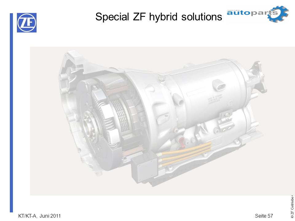
Spezielle ZF Hybridlösungen
56

57
Special ZF hybrid solutions
57 57
58
Parallelhybrid – Leistungsklassen ZF-Getriebe
Microhybrid Mildhybrid Vollhybrid HIS 8 HP EM Installierte elektrische Leistung 3-5 kW 4-20 kW kW Spannung 14-42 V mehr als 42 V V Verbrauchsreduzierung 3-5% ca. 15% 15-30% 1 Start-Stopp (alle)-/Generator-Funktion (Mild+Vollhybrid) 2 Rekuperieren 3 Boosten 4 Elektrisches Anfahren 5 Rein elektrisches Fahren 58
-/Generator-Funktion (Mild+Vollhybrid) 2 Rekuperieren. 3 Boosten. 4 Elektrisches Anfahren. 5 Rein elektrisches Fahren. 58.")
59
Parallel hybrid – output classes ZF Transmission
Micro hybrid Mild hybrid Full hybrid HIS 8 HP EM Installed electrical output 3-5 kW 4-20 kW kW Voltage 14-42 V More than 42 V V Fuel consumption reduction 3-5% About 15% 15-30% 1 start-stop (all)-/generator function (mild + full hybrid) 2 Recuperation 3 Boosting 4 Electrical starting 5 Purely electrical drive 59 59
-/generator function (mild + full hybrid) 2 Recuperation. 3 Boosting. 4 Electrical starting. 5 Purely electrical drive")
60
Einsparpotential der Hybridleistungsklassen
Vollhybridsysteme bieten das größte Einsparpotenzial. Gemessen an den geringeren Anschaffungskosten können sich aber auch die Einsparungen von Mikro- und Mildhybriden für Fahrer oder Flottenhalter rechnen.

61
Savings potential for the hybrid performance classes
Full hybrid systems offer the greatest savings potential. Measured against their lower purchase costs, this savings from micro and mild hybrids can also pay off for drivers or fleet operators.

62
Wieso Parallelhybrid? Die konzeptionelle Ausrichtung von ZF liegt im Pkw-Bereich auf dem Parallelhybrid Kostengünstigste Lösung mit größtem Kundennutzen. Der parallele Hybridantrieb ist vergleichsweise günstig zu produzieren, da er mit nur einer elektrischen Maschine auskommt Nur moderate elektrische Leistung im Antriebsstrang nötig Hohe Bauraumeffizienz gegenüber leistungsverzweigten Hybridgetrieben, weil nur eine elektrische Maschine erforderlich ist Hoher Wirkungsgrad Vorteil der Modularität Verschiedene Ausführungen können als „add-on-Modul“ auf vorhandene Automatikgetriebe aufgebaut werden Gleicher Bauraum nötig wie beim 8HP-Basisgetriebe 62

63
Why parallel hybrid? ZF is conceptually oriented to the parallel hybrid in the passenger car sector. Most affordable solution with the greatest customer benefits The parallel hybrid drive is comparably cost effective to produce, since it gets along with just one electric motor Only moderate electrical output in driveline necessary High installation space efficiency compared to power-split hybrid transmissions because only one electrical motor is required Higher efficiency Modularity advantage Various versions can be built upon available automatic transmissions as an “add-on module” Same installation space required as for the basic 8HP transmission 63 63

64
Namensdefinition für Wandler-Hybridgetriebe (Mildhybrid)
x HP xx H Ganganzahl Hybrid Baugröße Hydrodynamische Anfahrelement Planetenbauweise Beispiel: BMW Gen. 1.5: 8HP70H = Standardgetriebe mit E-Maschine 64

65
Definition of name for converter hybrid transmission (mild hybrid)
x HP xx H Number of gears Hybrid Size Hydrodynamic starting element Planetary design Example: BMW Gen. 1.5: 8HP70H = Standard transmission with e-motor 65 65

66
ZF Mildhybrid Beispiel: Mildhybrid
BMW Gen. 1.5: 8HP70H = Standardgetriebe mit E-Maschine

67
ZF mild hybrid Example: mild hybrid
BMW Gen. 1.5: 8HP70H = Standard transmission with e-motor

68
Namensdefinition für (Voll-) Hybridgetriebe
Hybridgetriebe (ohne Wandler): x P xx H Ganganzahl Hybrid Baugröße Planetenbauweise Beispiel: BMW Gen. 2.0: 6P28H / 8P45H / 8P70H Standardgetriebe mit E-Maschine; Anfahrelement ist die Bremse B Audi MLB : 8P55AF H = Front-Längs-Getriebe inkl. Allrad und Vorderachsdifferential zwischen Motor und E-Maschine; Anfahrelement ist die Bremse B 68
: x P xx H. Ganganzahl. Hybrid. Baugröße. Planetenbauweise. Beispiel: BMW Gen. 2.0: 6P28H / 8P45H / 8P70H Standardgetriebe mit E-Maschine; Anfahrelement ist die Bremse B. Audi MLB : 8P55AF H = Front-Längs-Getriebe inkl. Allrad und Vorderachsdifferential zwischen Motor und E-Maschine; Anfahrelement ist die Bremse B. 68.")
69
Definition of name for (full) hybrid transmission
Hybrid transmission (without converter): x P xx H Number of gears Hybrid Size Planetary design Example: BMW Gen. 2.0: 6P28H / 8P45H / 8P70H standard transmission with e-motor; brake B is the starting element Audi MLB : 8P55AF H = Front longitudinal transmission incl. all-wheel drive and front axle differential between engine and electric motor; brake B is the starting element. 69 69
: x P xx H. Number of gears. Hybrid. Size. Planetary design. Example: BMW Gen. 2.0: 6P28H / 8P45H / 8P70H standard transmission with e-motor; brake B is the starting element. Audi MLB : 8P55AF H = Front longitudinal transmission incl. all-wheel drive and front axle differential between engine and electric motor; brake B is the starting element")
70
ZF Vollhybrid BMW Gen. 2.0: 8P70H Standardgetriebe mit E-Maschine; Anfahrelement ist die Bremse B Audi MLB : 8P55AF H = Front-Längs-Getriebe inkl. Allrad und Vorderachsdifferential zwischen Motor und E-Maschine; Anfahrelement ist die Bremse B 70

71
ZF full hybrid BMW Gen. 2.0: 8P70H Standard transmission with e-motor;
brake B is the starting element Audi MLB : 8P55AF H = Front longitudinal transmission including all-wheel drive and front axle differential between engine and e-motor ; brake B is the starting element 71 71

72
ZF Vollhybridkonzept E-Maschine IAE Verbrennungsmaschine EM E-Pumpe
IAB K0 E-Pumpe Verbrennungsmaschine E-Maschine IAE EM = Elektromaschine, da Motorbetrieb und Generatorbetrieb möglich sind K0 = Trennkupplung IAE = integriertes Anfahrelement 72

73
ZF full hybrid concept E-motor IAE combustion engine EM E-pump
IAB K0 E-pump combustion engine E-motor IAE EM = Electric machine, since motor operation and generator operation are possible K0 = Separating clutch IAE = Integrated starting element 73 73

74
8P70H BMW Gen. 2 (Vollhybrid) Getriebeschema
Gang Bremse Kupplung Übersetz- ung i Gang- sprung A B C D E 1 2 3 4 5 6 7 8 4,696 3,130 2,104 1,667 1,285 1,000 1,50 1,49 1,26 1,30 1,29 1,19 7,05 Total R 0,839 1,25 -3,275 0,667 74

75
8P70H BMW Gen. 2 (full hybrid) Transmission schematic
Gear Brake Clutch Ratio i ratio step A B C D E 1 2 3 4 5 6 7 8 4.696 3.130 2.104 1.667 1.285 1.000 1.50 1.49 1.26 1.30 1.29 1.19 7.05 Total R 0.839 1.25 -3.275 0.667 75 75

76
*Continental Automotive Systems
Zusammenfassung ZF setzt auf den Hybridantrieb ZF setzt auf Parallelhybridlösungen ZF verfolgt wirtschaftliche Lösungen mit eher kleinen E-Maschinen ZF hat sich durch eine Partnerschaft mit CAS* verstärkt ZF ist mit allen wichtigen Kunden zum Thema Hybrid unterwegs ZF entwickelt bereits Gen 3.0 als Plug-In Hybrid zur Erfüllung Vorgabe China. „In 2014 muß jeder Fahrzeughersteller einen Plug-In Hybrid anbieten“ Gen 1.5 BMW/Conti Gen 2.0 BMW/RB – Audi/Conti *Continental Automotive Systems 76

77
*Continental Automotive Systems
Summary ZF focuses on hybrid drive ZF focuses on parallel hybrid solutions ZF is pursuing economical solutions with rather small e-motors ZF is stronger due to a partnership with CAS* ZF is active with all its important customers on the hybrid issue ZF already develops generation 3.0 as a plug-in Hybrid. „In 2014 every vehicle manufacturer must have a hybrid plug-in car in his portfolio who wants to sell cars in China. Gen 1.5 BMW/Conti Gen 2.0 BMW/RB – Audi/Conti *Continental Automotive Systems 77 77

78
Besten Dank für Ihre Aufmerksamkeit
78

79
Thank you very much for your attention
79

80
Ende 80

81
The End 81

Ähnliche Präsentationen


>")

 U N I V E R S I T Ä T H A M B U R G November 2011.>")
 U N I V E R S I T Ä T H A M B U R G November 2011.>")

Media Landesanstalt für Kommunikation Baden-Württemberg (LFK) Landeszentrale für Medien und Kommunikation.>")


