Präsentation herunterladen
Die Präsentation wird geladen. Bitte warten

1
Der LHC Proton-Proton Collider und seine supraleitende Magnete Rüdiger Schmidt - CERN Universität Wien Februar 2002

2
2 Mit dem LHC will man am CERN möglichst intensive Teilchenstrahlen bei einer Energie von 7 TeV auf kleinstem Raum zur Kollision bringen, um möglichst viele neue Teilchen zu erzeugen

3
3 LEP Event

4
4 10 8 events / sekunde LHC Event

5
5

6
6 29 Oktober 2002Rüdiger Schmidt Was ist der LHC ? u Der nächste Beschleuniger, der in einen neuen Energiebereich vorstossen wird - 7 TeV/c => Neue Physik (Higgs Teilchen) u Proton-Proton Collider mit sehr hoher Luminosität und Energie Ablenkmagnetfeld in Bogen : u Schwerionen - Collider mit sehr hoher Energie u LHC und die CERN Infrastruktur u im LEP Tunnel, Länge etwa 27 km, 8 Sektionen mit 4 Experimenten u Optimale Ausnutzung der existierenden CERN Beschleuniger für den LHC (SPS, PS, Booster, LEAR, Linacs, Ionenquellen) 1982 : Erste Studien zum LHC Projekt 1994 : Genehmigung durch den CERN Council 1996 : Entscheidung zum Bau des Beschleunigers 2006/2007: Inbetriebnahme mit Strahl
 u Proton-Proton Collider mit sehr hoher Luminosität und Energie Ablenkmagnetfeld in Bogen : u Schwerionen - Collider mit sehr hoher Energie u LHC und die CERN Infrastruktur u im LEP Tunnel, Länge etwa 27 km, 8 Sektionen mit 4 Experimenten u Optimale Ausnutzung der existierenden CERN Beschleuniger für den LHC (SPS, PS, Booster, LEAR, Linacs, Ionenquellen) 1982 : Erste Studien zum LHC Projekt 1994 : Genehmigung durch den CERN Council 1996 : Entscheidung zum Bau des Beschleunigers 2006/2007: Inbetriebnahme mit Strahl.")
7
7 Das CERN ist das führende europäische Forschungsinstitut für Teilchenforschung Es liegt bei Genf im schweizerischen - französischen Grenzgebiet Österreich ist eines der CERN Mitgliedsländer, und somit wesentlich am Bau des LHC beteiligt

8
LHC proton-proton Collider 7 TeV/c im LEP Tunnel LEP: e+e- 104 GeV/c (1989-2000) Umfang 26.8 km Injection from SPS at 450 GeV/c
 Umfang 26.8 km Injection from SPS at 450 GeV/c")
9
9 8 arcs with a length of about 2.8 km 8 straight sections with a length of about 600 m Straight sections are used for physics experiments, and for accelerator systems Beam cleaning, beam dump, RF-acceleration, and beam instrumentation

10
10 Übersicht u LHC Parameter u Energie und Luminosität u LHC Layout u Supraleitende Magnete für den LHC u Machine Protection Elektromagnetismus und Relativitätstheorie Thermodynamik Mechanik Quantenmechanik Physik nichtlinearer Systeme Festkörperphysik und Oberflächenphysik Teilchenphysik und Strahlungsphysik + Ingenieurwissenschaften

11
11 Energie u LEP u Ablenkfeld B = 0.123 tesla u Maximaler Impuls 103 GeV/c u Radius 2805 m u Elektromagnete teilweise aus Beton u LHC u Ablenkfeld B = 8.33 tesla u Maximaler Impuls 7000 GeV/c u Radius 2805 m u Magnetfeld mit Eisenmagneten maximal 2 tesla, daher werden supraleitende Magnete benötigt B = p / e 0 R

12
12 Energy in the magnet system: 11 GJ u In case of failure, extract energy with a time constant of up to about 100 s Drop 35 tons from 28 km Energy stored in Magnets The energy in the magnets corresponds to an energy that melts 7500 kg of copper

13
13 29 Oktober 2002Rüdiger Schmidt Luminosität L = N 2 f n b / 4 x y mit N......... Teilchen im Paket f......... Umlauffrequenz n b......... Anzahl der Paket x y... Strahldimensionen am Wechselwirkungspunkt Anzahl der Neuen Teilchen: Das Ziel ist eine Luminosität von etwa 10 34 [cm -1 s -2 ] u LEP (e+e-) : 3-4 10 31 [cm -1 s -2 ] u Tevatron (p-pbar) : 3 10 31 [cm -1 s -2 ] u B-Factories: > 10 33 [cm -1 s -2 ] Wie lässt sich so eine hohe Luminosität erreichen ?
 : [cm -1 s -2 ] u Tevatron (p-pbar) : [cm -1 s -2 ] u B-Factories: > [cm -1 s -2 ] Wie lässt sich so eine hohe Luminosität erreichen .")
14
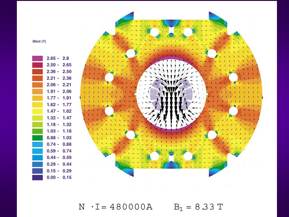
14 29 Oktober 2002Rüdiger Schmidt Large number of bunches 2835 bunches - spacing of about 25 ns Minimum beam size at IP of 0.5 m u Bunch structure with 25 ns spacing u Experiments: more than 1 event / collision u Vacuum system: photo electrons u Crossing angle to avoid long range beam beam interaction u Interaction Region quadrupoles with gradient of 250 T/m and 70 mm aperture

15
15 29 Oktober 2002Rüdiger Schmidt Beam current and energy stored in the beam Many bunches - Current in one beam about 0.5 A Energy in one beam about 330 MJ u Dumping the beam in a safe way u Beam induced quenches (when 10 -7 of beam hits magnet at 7 TeV) u Beam stability and Magnet Field quality u Beam cleaning (Betatron and momentum cleaning) u Synchrotron radiation - power to cryogenic system u Radiation, in particular in experimental areas from beam collisions (beam lifetime is dominated by this effect)
 u Beam stability and Magnet Field quality u Beam cleaning (Betatron and momentum cleaning) u Synchrotron radiation - power to cryogenic system u Radiation, in particular in experimental areas from beam collisions (beam lifetime is dominated by this effect)")
16
16 Challenges: Energy stored in the beam R.Assmann One beam, nominal intensity (corresponds to an energy that melts 500 kg of copper) Momentum [GeV/c] Energy stored in the beam [MJ] x 200
![16 Challenges: Energy stored in the beam R.Assmann One beam, nominal intensity (corresponds to an energy that melts 500 kg of copper) Momentum [GeV/c] Energy stored in the beam [MJ] x 200](http://images.slideplayer.org/3/919599/slides/slide_16.jpg "16 Challenges: Energy stored in the beam R.Assmann One beam, nominal intensity (corresponds to an energy that melts 500 kg of copper) Momentum [GeV/c] Energy stored in the beam [MJ] x 200")
17
17 Energy in two LHC Beams: 700 MJ Dump the beams in case of failure within 89 s after dump kicker fires u The beam dump is the onle element in the LHC that can stand the beam impact Energy in Beams Drop it from 2 km One beam, nominal intensity corresponds to an energy that melts 500 kg of copper

18
18 Summary LHC Parameter

19
Momentum at collision 7 TeV/c Momentum at injection 450 GeV/c Dipole field at 7 TeV 8.33 Tesla Circumference26658m Luminosity 10 34 cm -2 s -1 Number of bunches 2808 Particles per bunch 1.1 10 11 DC beam current 0.56 A Stored energy per beam 350 MJ Normalised emittance3.75 µm Beam size at IP / 7 TeV15.9µm Beam size in arcs (rms)300µm Arcs: Counter-rotating proton beams in two- in-one magnets Magnet coil inner diameter 56 mm Distance between beams 194 mm High beam energy in LEP tunnel superconducting NbTi magnets at 1.9 K High luminosity at 7 TeV very high energy stored in the beam beam power concentrated in small area Limited investment small aperture for beams
300µm Arcs: Counter-rotating proton beams in two- in-one magnets Magnet coil inner diameter 56 mm Distance between beams 194 mm High beam energy in LEP tunnel superconducting NbTi magnets at 1.9 K High luminosity at 7 TeV very high energy stored in the beam beam power concentrated in small area Limited investment small aperture for beams")
20
20 LHC Layout

21
21 Layout of the LHC ring: 8 arcs, and 8 long straight sections Momentum Cleaning Betatron Cleaning Beam dump system RF + Beam instrumentation One sector = 1/8

22
22

23
23 Periodischer Aufbau: FODO Zelle u Dipol- und Quadrupol Magnete –Teilchenbahn stabil für Teilchen mit Sollimpuls u Sextupol Magnete –zur Korrektur von Teilchenbahnen für Teilchen mit Impulsabweichung –Teilchenbahn stabil für kleine Amplituden (etwa 10 mm) u Multipol-Korrekturmagnete –Sextupol - und Dekapolkorrekturmagnete am Ende der Dipolmagnete –Teilchenbahnen können instabil werden (selbst nach vielen Umläufen kann eine Teilchenbahn plötzlich instabil werden, z.B. 10 6 )
.")
24
24 Bahnstabilität durch Supraleitende Magnete - Quadrupol- und Multipolfelder

25
25 29 Oktober 2002Rüdiger Schmidt Crossing angle for multibunch operation u Focusing quadrupole for beam 1, defocusing for beam 2 u High gradient quadrupole magnets with large aperture (US-JAPAN) u Total crossing angle of 300 mrad Beam size at IP 16 m, in arcs about 1 mm
 u Total crossing angle of 300 mrad Beam size at IP 16 m, in arcs about 1 mm")
26
26 29 Oktober 2002Rüdiger Schmidt Layout of insertion for ATLAS and CMS

27
27 1232 main dipoles + 3700 multipole corrector magnets 392 main quadrupoles + 2500 corrector magnets Regular arc: Magnets

28
28 Regular arc: Cryogenics Supply and recovery of helium with 26 km long cryogenic distribution line Static bath of superfluid helium at 1.9 K in cooling loops of 110 m length Connection via service module and jumper

29
29 Insulation vacuum for the cryogenic distribution line Regular arc: Vacuum Insulation vacuum for the magnet cryostats Beam vacuum for Beam 1 + Beam 2

30
30 Vacuum chamber Beam vacuum system Beam screen is required for most of the machine Beam screen with cooling channels and pumping slots Ensures vacuum stability Captures synchrotron radiation at 5-20 K Beam stability => Low impedance: thin copper layer Electron cloud effects: - Minimise reflectivity - Beam scrubbing (as in SPS)
")
31
31 One of 1800 interconnection between two superconducting magnets: LHC 6 superconducting bus bars 13 kA for B, QD, QF quadrupole 20 superconducting bus bars 600 A for corrector magnets (minimise dipole field harmonics) 42 sc bus bars 600 A for corrector magnets (chromaticity, tune, etc….) + 12 sc bus bars for 6 kA (special quadrupoles) 13 kA Protection diode To be connected: Beam tubes Pipes for helium Cryostat Thermal shields Vacuum vessel Superconducting cables
 42 sc bus bars 600 A for corrector magnets (chromaticity, tune, etc….) + 12 sc bus bars for 6 kA (special quadrupoles) 13 kA Protection diode To be connected: Beam tubes Pipes for helium Cryostat Thermal shields Vacuum vessel Superconducting cables")
32
32 Dipolmagnete für den LHC 1232 Dipolmagnete Länge 15 m Magnetfeld 8.3 T 2 Strahlrohre mit 56 mm Öffnung

33
33 29 Oktober 2002Rüdiger Schmidt Spulenanordnung für Dipolmagnete

34
34 29 Oktober 2002Rüdiger Schmidt Ansicht des Dipolmagnet im Kryostat

35
Vakuumröhre für Strahlen Supraleitende Spule Nichtmagnetische Stahlklammern Ferromagnetisches Eisen Stahlzylinder für Helium Isoliervakuum Stützfüsse Vakuumtank

36
Two - in One Magnet

38
38 Die Entdeckung der Supraleitung 1908 -- Kamerlingh Onnes verflüssigt Helium. 1911 -- R-T Messung für Quecksilber ? "…. Mercury has passed into a new state, which on account of its extraordinary electrical properties may be called the superconductive state …." Copyright A.Verweij

39
39 Magnetfeld - Stromdichte - Temperatur Materialeigenschaften: Tc kritische Temperatur Bc kritisches Feld Produktionsprozess: Jc kritische Stromdichte Bc Tc Niedrigere Temperatur grössere Stromdichte Typisch: für NbTi: 2000 A/mm2 @ 4.2K, 6T Für 10 T, Operation unterhalb 1.9 K erforderlich Copyright A.Verweij

40
40 Typische Supraleiter Das hohe kritische Feld der Supraleiter Typ II lässt den Bau von Magneten mit hoher Feldstärke zu 1962 -- Entwicklung von kommerziellen Niobium-Titan (NbTi) supraleitenden Drähten. Charakterisierung von Supaleitern durch: u Temperatur u Magnetfeld u Stromdichte Copyright A.Verweij

41
41 Helium: Phasendiagramm T>T : HeI T<T : HeII (superflüssiges Helium) T =2.17 K LHC: T=1.9 K P 1.2 bar Copyright A.Verweij
 T =2.17 K LHC: T=1.9 K P 1.2 bar Copyright A.Verweij")
42
42 Helium Parameter T Spezifische Wärme von Helium als Funktion von T Phasenübergang bei 2.18 Kelvin Superflüssiges Helium (He II) Copyright A.Verweij
 Copyright A.Verweij")
43
z.B durch Teilchenverluste Erwärmung If T > Tcritical Quench T=temperature margin (1.4 K for LHC) Tc Bc Quench = Übergang Supraleitung Normalleitung Spezifische Wärme
 Tc Bc Quench = Übergang Supraleitung Normalleitung Spezifische Wärme")
44
44 Quench t Bewegung des Supraleiters um einige m kann einen Quench auslösen t Strahlverluste von etwa 10 -6 können die Dipolmagnete bei 7 TeV zum Quenchen bringen t Der Supraleiter wird mit Kupfer stabilisiert - der Widerstand von Kupfer unterhalb einer Temperatur von 30 K ist etwa 1/100 im Vergleich zum Widerstand bei 300 K Der Magnetstrom muss im Quenchfall schnell abgeschaltet werden (etwa 100 ms)
")
45
45 Ein supraleitender Draht 1 mm 6 m Typischer Wert für maximalen Strom bei 8 T, 1.9 K: 800 A Copyright A.Verweij

46
46 LHC: Superconducting Magnets Dipole assembly in industry Arc 15-m dipoles and quadrupoles Insertion dipoles and quadrupoles Corrector magnets

47
47 Cryostating and measurements (main dipoles and other magnets) SMA18 cryostating hall at CERN for installing dipole magnets into cryostats SM18: 12 measurement stations are prepared for cold tests of possibly all superconducting magnets A.Rijllard
 SMA18 cryostating hall at CERN for installing dipole magnets into cryostats SM18: 12 measurement stations are prepared for cold tests of possibly all superconducting magnets A.Rijllard")
48
48 Sextupoles and decapoles to be installed at the extremities of the main dipoles Delivery must precede dipole magnet fabrication (contribution from India and fabrication in industry) Corrector magnet fabrication - construction for 11 types of magnets started L. Garcia-Tabares

49
49 Machine protection: Beam energy Beam Cleaning: Beam Cleaning: Capture particles in the warm sections of the LHC with an efficiency of better than 99.9% to avoid losses that could quench superconducting magnets In case of equipment failure, beam instabilities etc: Capture initial beam losses that could damage LHC equipment Beam Loss Monitors close to collimators and other aperture restrictions produce a fast and reliable signal to dump the beam if beam losses become unacceptable For 7 TeV: fast beam loss between 10 6 and 10 7 protons could quench a dipole magnet The beam dump block is the only system that can stand the full 7 TeV beam - 3·10 14 The beam dump block is the only system that can stand the full 7 TeV beam - 3·10 14 protons

50
50 Beam Cleaning System Collimators close to the beam are required during all phases of operation Sophisticated beam cleaning system with many collimators has been designed limit aperture to about 6-10 Together with the Beam Loss Monitors produce a fast and reliable signal to dump the beam if beam losses become unacceptable

51
51 +- 3 1.3 mm Beam +/- 3 sigma 56.0 mm Beam in vacuum chamber at 7 TeV

52
Example for failure at 450 GeV Assume that the current in one orbit corrector magnet is off by 10% of maximum current (Imax = 60 A) 12.0 mm 16.0 mm Beam+/- 3 sigma Beam+/- 3 sigma and orbit corrector 10 % / 100 % of Imax 56.0 mm Ralphs EURO
 12.0 mm 16.0 mm Beam+/- 3 sigma Beam+/- 3 sigma and orbit corrector 10 % / 100 % of Imax 56.0 mm Ralphs EURO")
53
Beam+/- 3 sigma 56.0 mm 1 mm +/- 8 sigma = 4.0 mm Example: Setting of collimators at 7 TeV - with luminosity optics Beam must always touch collimators first ! Collimators might remain at injection position during the energy ramp Ralphs EURO Collimators at 7 TeV, squeezed

54
54 Particles that touch collimator after failure of normal conducting D1 magnets After about 13 turns 3·10 9 protons touch collimator, about 6 turns later 10 11 protons touch collimator V.Kain Dump beam level 10 11 protons at collimator

55
55 Beam Loss Monitors Primary strategy for protection: Beam loss monitors at collimators continuously measure beam losses u Beam loss monitors indicate increased losses => MUST BE FAST After a failure: u Beam loss monitors break Beam Permit Loop u Beam dump sees No Beam Permit => dump beams In case of equipment failure, enough time is available to dump the beam before damage of equipment - including all magnets and power converters - but issues such a General Power Cut etc. are still being addressed

56
56 Prototype LHC cell: the 110 m long String 2 Full size model of one LHC cell (six dipoles and two quadrupoles) 2001: 3 dipoles and 2 quadrupoles Cooled down to 1.9 K and one dipole and two quadrupole circuits were powered to nominal current Cell has been completed (now six dipoles) and is today being cooled down Experiment were performed in 2001 and will continue soon
 2001: 3 dipoles and 2 quadrupoles Cooled down to 1.9 K and one dipole and two quadrupole circuits were powered to nominal current Cell has been completed (now six dipoles) and is today being cooled down Experiment were performed in 2001 and will continue soon")
57
57 String 2: First Powering of dipole magnets

58
58 String 2: Start of the LHC dipole circuit ramp (0-20s) simulates ramp after injection of beam at 450 GeV 50 ppm of full current = 350 MeV Q.King et al. ICALEPS 2001

59
59 String 2: LHC dipole circuit ramp (0- 4s) 2 ppm = 14 MeV Results were achieved with a new method of digital regulation together with an ultra high precision current measurement system
 2 ppm = 14 MeV Results were achieved with a new method of digital regulation together with an ultra high precision current measurement system")
60
60 Integration and Installation u Space in tunnel and underground areas is limited u Equipment for many systems need to be installed u 3-D computer model for tunnel and underground areas

61
61 Conclusions The LHC is installed and commissioned in eight (rather) independent sectors - that allows for activities to be performed in parallel Installation of LHC started with general services March 2002 l Civil engineering is nearly completed l Most contracts with industry for equipment supply have been awarded l Fabrication of equipment under the responsibility of other labs goes well Planning can now be based on deliveries and contractual documents
 independent sectors - that allows for activities to be performed in parallel Installation of LHC started with general services March 2002 l Civil engineering is nearly completed l Most contracts with industry for equipment supply have been awarded l Fabrication of equipment under the responsibility of other labs goes well Planning can now be based on deliveries and contractual documents")
62
62 Conclusions Fabrication of equipment Installation of completed components Very thorough commissioning of the hardware systems starting in 2005, sector by sector, as key for successful fast start up with beam From now to 2006 String 2 gave us a lot of confidence as we observed a smooth commissioning of the hardware systems In 2006 - one beam injected and transported across two sectors (25% of the ring) Start-up with two beams in spring 2007
 Start-up with two beams in spring 2007")
63
63 29 Oktober 2002Rüdiger Schmidt LHC injector complex - pre-accelerators exist

64
64 Transfer Lines SPS - LHC Two new transfer line tunnels from SPS to LHC are being built. The beam lines use normal conducting magnets Length of each line: about 2.8 km Magnets are all available, made by BINP / Novosibirsk Commissioning of the first line for 2004 Dipole magnets waiting for installation

65
65 Accelerator physics and operation u Dynamic aperture of 11 sigma: for all magnets the maximum tolerated multipoles were specified u Preparations based on very well controlled slow ramp with PELP function (parabolic, exponential, linear and parabolic) u Accurate modelling of beam dynamics through the cycle u Magnetic multipoles u Dynamic effects in superconducting magnets u Beam beam effects - head on / parasitic crossings u Preparation of slow feedback for tune and orbit, and possibly chromaticity - prototyping at the SPS u Online magnetic measurements (multipole factory) for feed-forward to corrector circuits
 u Accurate modelling of beam dynamics through the cycle u Magnetic multipoles u Dynamic effects in superconducting magnets u Beam beam effects - head on / parasitic crossings u Preparation of slow feedback for tune and orbit, and possibly chromaticity - prototyping at the SPS u Online magnetic measurements (multipole factory) for feed-forward to corrector circuits")
66
66 Powering and Quench Protection u Almost 1800 circuits from 60 A to 24 kA distributed around the 27 km LHC accelerator => 1800 Power Converter u The eight sectors of the LHC are largely independent - accurate tracking of current is required u Very high performance is needed for the 24 main circuits with main dipole and quadrupole magnets at I = 12 kA u For the main circuits the current needs to be controlled at the ppm level (12 mA at 12 kA) u Protection of 8000 magnets, 1800 High Temperature Superconductor current leads, and a large number of superconducting bus bars
 u Protection of 8000 magnets, 1800 High Temperature Superconductor current leads, and a large number of superconducting bus bars")
67
67 Machine protection: Machine protection: Magnet energy Energy in dipole magnets: 10 GJoule … per sector reduced to 1.3 GJoule Uncontrolled release of energy is prevented: Fire quench heaters Current by-passes magnet via power diode Extract energy by switching a resistor into the circuit - the resistor with a mass of eight tons is heated to 300 °C All components of the system have been validated, and production started (part in collaboration with Russia and India) 13 kA switches from Protvino Russia
 13 kA switches from Protvino Russia")
Ähnliche Präsentationen


Media Landesanstalt für Kommunikation Baden-Württemberg (LFK) Landeszentrale für Medien und Kommunikation.>")


 4th Planet Formation Workshop MPIA, 1 st March 2006 Discovery of a cool 5.5 Earth-mass planet through gravitational.>")


