Präsentation herunterladen
Die Präsentation wird geladen. Bitte warten

1
Tracking session Jochen Markert, IKF Frankfurt
![]()
2
Topics Activities Lepton efficiency estimation
Implementation of efficiency in digitizer Dependency of efficiency on the ionization of the particle track Number of wires in cluster Estimation of layer efficiency Comparison of different tracking code versions Reconstruction of opening angle of lepton pairs Dependency of resolution on the ionization of the particle track PID with MDC: energy loss

3
Activities in MDC analysis
CAL1 Jochen Khaled Yvonne Pulser method for offset calibration Tuning of offsets and second iteration of calibration weeks Done for pp CAL2 New GARFIELD parameters Cathode planes instead of cathode wires short term Analytical description of xt-correlation and errors DELAYED! Short term Medium term TRACK Segment fitter Vladimir Restructuring of the tracking code Improvement of minimization Improvement of performance Tuning of parameters Done Thierry Emilie Jean-Lois Investigation on MDCIV Check of geometry Alignment Alexander Alignment for inner and outer modules Alignment with photo modeler (MDCs + Magnet) Alignment with cosmics Alignment of META Geydar Wire layer offsets Layer thickness (MDCIII+IV) Done but no clear results
 Alignment with cosmics. Alignment of META. Geydar. Wire layer offsets. Layer thickness (MDCIII+IV) Done but no clear results.")
4
Future tasks First priority: Efficiency correction
Tracking for high multiplicities + CPs, needed for final DSTs of SEP05!!! CODE STABILITY!!!!! (we lost weeks for debugging!) Second priority: (several weeks) Time offsets from pulser method (Khaled) Development of “ideal tracking” MDC part ( done by Vladimir) Other detectors ? Development of embedding of simulated tracks in real events MDC part already existing Investigation of events with very large unphysical multiplicity How many ? Definition of reasonable numbers of tracks (SIM/DATA) Fixing of geometry of outer MDCs Wire angles , layer thickness (Geydar) Wire layer offsets (Geydar + Thierry + Emilie) Measurements on MDCIV (Thierry + Jean-Lois) Optimization of cal2 parameters Smoother values + analytical description (Jochen) Retrieving parameters for out MDCs from DATA (Thierry + Emilie)
 Second priority: (several weeks) Time offsets from pulser method (Khaled) Development of ideal tracking MDC part ( done by Vladimir) Other detectors Development of embedding of simulated tracks in real events. MDC part already existing. Investigation of events with very large unphysical multiplicity. How many Definition of reasonable numbers of tracks (SIM/DATA) Fixing of geometry of outer MDCs. Wire angles , layer thickness (Geydar) Wire layer offsets (Geydar + Thierry + Emilie) Measurements on MDCIV (Thierry + Jean-Lois) Optimization of cal2 parameters. Smoother values + analytical description (Jochen) Retrieving parameters for out MDCs from DATA (Thierry + Emilie)")
5
Influence on the tracking efficiency
MDC efficiency (cell efficiency: gas, thresholds, noise). MDC hardware problems (missing MBo, …). Calibration quality Alignment Track finder efficiency. Momentum reconstruction efficiency. Matching efficiency. Cuts efficiency (chi2 cut etc.). Particle identification efficiency. …
![]()
6
Properties of wire clusters
CPR by properties of cluster size and number of wires in cluster Tuned to get good agreement between simulation and experiment

7
Cell efficiency in digitizer
Cell efficiency not depending on energy loss of particle in digitizer

8
Mean number of wires in cluster
NOV01

9
MDCI

10
MDCII

11
MDCIII

12
MDCIV

13
Detection efficiency of MDC
Particle Layer 1 Layer 2 Layer 3 Layer 4 Layer 5 Layer 6 Method: Efficiency of Layer: A particle track has to be detected at least once per NOV01 MDCI MDCII efficiency of wire layer better than als 89% (MIPS) Segment theoretical better than 98,4% !????? Good agreement with laboratory measurement
 Segment theoretical better than 98,4% ! Good agreement with laboratory measurement.")
14
Layer efficiency including the wires which have been removed by tukey weights
NOV02

15
Layer efficiency from fit accepted wires
NOV02 Lay MDC I II 1 0.75 0.90 2 0.68 0.91 3 0.69 4 0.70 5 6 0.66 0.85 MDCI MDCII

16
MDC I p-blue, --red MDC II
SEP05

17
Ratio fitted segments/all segments of lepton pairs
Comparison for Exp URQMD PLUTO Full pair analysis and background rejection applied!

18
Comparison of fitting track fitter for different HYDRA versions
Subtitle: long story about nothing

19
Problem description Efficiency of track reconstruction of lepton pairs
Rumors about change in reconstruction efficiency of pairs (10%) observed by Laura between old calculation with HYDRA v7_05b and new v7_07/v7_08
 observed by Laura between old calculation with HYDRA v7_05b and new v7_07/v7_08.")
20
Method Tracking + ideal tracking parallel (HMdcTaskSet/HMdcIdealTracking) Filling of ntuple with HMdcTrackingEff Efficiency calculation: Input Pluto Sim Nov02 Reference sample ideal segments (both inner and outer segments + Meta hits found in GEANT) Pairs definition : inner segments cluster/fitted, no condition on outer segments, opening angle cut of 9 degree Efficiency: found pairs / ideal pairs
![]()
21
opening angle distribution of lepton pairs
Comparison of different code versions of tracking

22
Efficiency of lepton pairs as function of opening angle
1ook events in simulation No significant efficiency between the different versions

23
Opening angle reconstruction
Cut on opening angle 9 degree : Difference between GEANT angle accepted reconstructed angle accepted gives 5% more accepted pairs.

24
Reconstruction of invariant Mass

25
Position resolution of the track reconstrution
Resolution of the drift cells Drift time residuals spatial resolution : Dependence on the primary ionization clearly visual Drift cell resolution better than 150 m design value MDCII NOV01 Data Position resolution of the reconstruction Meets requirements

26
Energy loss measurement with MDCs ?
Contra: MDCs measure drift times not pulse height „Low-mass“ - concept of MDCs not optimized for dE/dx - measurement with high resolution Measurement of energy loss through width of the drift time signal („Time above Threshold“, t2-t1) as measure of deposed charge ? 1 1 T. Akesson et al. Nucl. Inst. and Methods, A(474):172–187, 2001.
 as measure of deposed charge 1. 1 T. Akesson et al. Nucl. Inst. and Methods, A(474):172–187,")
27
Normalization of signal width
Impact angle Drift cell Impact angle , distance from wire Drift chamber Gas amplification (HV) Track segment Mean over all cells
 Track segment. Mean over all cells.")
28
Normalized and averaged Signal width
Protons and pions can be separated Electrons and pions overlay deuterons and protons overlay

29
Resolution of signal width measurement
resolution for protons 6-9 % resolution for pions % % p % d % % Data Resolution comparable with dE/dx measurement through pulse height!

30
Correlation of signal width with dE/dx
Fitted with F(dE/dxBethe-Bloch) Correlation of signal width measurement with dE/dx property of signal shape and readout electronic1 Good agreement for protons and pions 1 L. Ratti et al., WCC 2004, Vienna, Vortrag 2004.
 Correlation of signal width measurement with dE/dx. property of signal shape and readout electronic1. Good agreement for protons and pions. 1 L. Ratti et al., WCC 2004, Vienna, Vortrag")
32
The drift cell Dimension of the drift cells 5x5 - 10x14 mm2
Field wire Cathode wires Amplification area Sense wire Dimension of the drift cells 5x5 - 10x14 mm2 Gas mixture He/i-Butan (60/40) Simulation of the drift cells with GARFIELD - Geometry, Field, Drift MAGBOLZ - Gas properties HEED Primary ionization
 Simulation of the drift cells with GARFIELD - Geometry, Field, Drift. MAGBOLZ - Gas properties. HEED - Primary ionization.")
33
Simulation with GARFIELD
x [cm] y [cm] drift Simulation: Inhomogeneous electric Field inside the drift cell VDrift depending on electric field Inhomogeneous distribution of VDrift inside drift cell

34
Time distance For track reconstruction space points are needed, but MDCs measure drift times Relation between drift time and minimal distance of the particle track from sense wire has to be known

35
x-t- correlation 2-dimensional drift cell model:
Simulation of the drift signals using GARFIELD Parameterization through impac angle and minimum distance from wire Implementation into track reconstruction and GEANT - Simulation

36
Normalization of signal width (t2-t1)
Data Nov01 MDCII Normalization with one curve per impact angle step (5°) MDCI/II normalized to the same value Deviation for higher momenta
 MDCI/II normalized to the same value. Deviation for higher momenta.")
37
Normalization of signal width
Impact angle (), minimal distance from wire All chamber types normalized to common value Normalization point at 450 MeV/c Inner segment (MDCI/II) : Good agreement at small momenta Deviation at higher momenta MDCIII/IV show different behavior as MDCI/II (statistic/geometry/working point?) Data Nov01 Nomalization
, minimal distance from wire. All chamber types normalized to common value. Normalization point at 450 MeV/c. Inner segment (MDCI/II) : Good agreement at small momenta. Deviation at higher momenta. MDCIII/IV show different behavior as MDCI/II (statistic/geometry/working point ) Data Nov01. Nomalization.")
38
Comparison of dE/dx resolution with other experiments
Empiric formula for calculation of dE/dx resolution (MIPS): A. H. Walenta et al. Nucl. Instr. Methods, 161(45), 1979 dE/dx resolution for gas mixtures with large fraction of hydrocarbon (Quencher) better as predicted
: A. H. Walenta et al. Nucl. Instr. Methods, 161(45), dE/dx resolution for gas mixtures with large fraction of hydrocarbon (Quencher) better as predicted.")
39
The drift time measurement
The drift time measurement started by the induced signal at the sense wire The signal gets amplified, shaped and discriminated The TDC measures the time between the edges of the logic signal and an external signal („common stop“ (CMS))
)")
40
Calibration of drift times

41
Track reconstruction Track fitting:

42
Energy loss measurement with MDCs
Energy loss calculation with GARFIELD Protons above 1GeV nearly minimal ionizing Protons at 100 MeV have 4 times larger dE/dx compared to ,e,

43
Simulation with GARFIELD

44
Impact of a asymmetrical cathode voltage
Cathode voltage -1000V instead t -1750V (MDCI in NOV01) Electric field deformed near the cathode y [cm] x [cm]
 Electric field deformed near the cathode. y [cm] x [cm]")
45
Impact of a asymmetrical cathode voltage
Relative error of the drift time measurement compared to normal working conditions is large Affected wire layers should nor be used in analysis

46
Analysis of the GARFIELD Signals
„Leading“- and „trailing edge“ –times are calculated at a give threshold Distribution of drift times of 100 tracks for a given parameter set (minimal distance, angle) are accumulated and the mean and sigma of the time measurement calculated
 are accumulated and the mean and sigma of the time measurement calculated.")
47
Shape of the signals Broad arrival time distribution near sense wire
slow electrons from the edge of the drift cell

48
Anzahl der Cluster pro cm als Funktion der Teilchenenergie
Nimmt mit steigender Energie ab Unterschiede zwischen Teilchenspezies ver-schwinden bei hohen Energien

49
Anzahl der Cluster pro cm als Funktion der Gasmischung
Ändert sich mit der Zusammensetzung des Zählgases Nimmt mit steigendem i-Butan Anteil zu

50
Signalbreite versus Teilchenimpuls
Single cell Single cell Data Nov01 Messung einzelner Driftzellen (oberer Reihe) Normalisierte Signalbreite für ein Segment (unten) Segment
 Normalisierte Signalbreite für ein Segment (unten) Segment.")
51
Korrelation der Signalbreite mit dE/dx
Data Freie Anpassung mit Korrelation der Signalbreitenmessung gegenüber dE/dx Eigenschaft der Ausleseelektronik1 Gute Übereinstimmung für Protonen und Pionen 1 L. Ratti et al., WCC 2004, Vienna, Vortrag 2004.

52
Zeitauflösung als Funktion des Schwellenwertes
Zeitauflösung verschlechtert sich mit steigender Schwelle Der Effekt ist nahe am Auslesedraht und in den Randbereichen der Driftzelle stärker ausgeprägt DUBNA

53
Zeitauflösung als Funktion der Teilchenenergie
Zeitauflösung verschlechtert sich mit steigender Energie Der Effekt ist nahe dem Auslesdraht und in den Randbereichen der Driftzelle stärker ausgeprägt DUBNA

54
Zeitauflösung als Funktion der Teilchenenergie
Zeitauflösung verschlechtert sich mit steigender Energie Data Nov01 impact 90°

55
Zeitauflösung als Funktion der Schwelle
Änderungen in der Zeitauflösung führen zu einer Verschiebung der Driftzeitmessung mit steigender Energie resolution in the middle of the cell DUBNA

56
Verschiebung in der Driftzeitmessung
xt – Relation für 100/1000 MeV Protonen Effekt ist nahe dem Auslesedraht und in den Randbereichen der Driftzelle stärker ausgeprägt DUBNA

57
Verschiebung in der Driftzeitmessung
Änderungen in der Zeitauflösung (verursacht durch Änderungen der Ionisation) führt zu einer Verschiebung der Driftzeitmessung mit zunehmender Energie Timing shift in the middle of the cell DUBNA
 führt zu einer Verschiebung der Driftzeitmessung mit zunehmender Energie. Timing shift in the middle of the cell. DUBNA.")
58
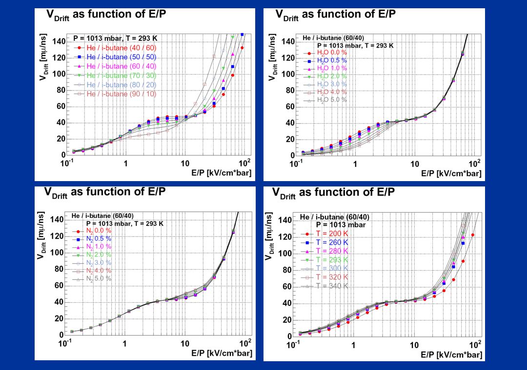
VD als Funktion der Gasmischung
Driftgeschwindigkeit in der Mitte der Driftzelle i-Butan verringert die Driftgeschwindigkeit

59
Relativer Fehler der Driftzeitmessung

60
VD als Funktion des Gasdruckes
Driftgeschwindigkeit in der Mitte der Driftzelle Driftgeschwindigkeit verringert sich mit steigendem Druck

61
Relativer Fehler der Driftzeitmessung

62
VD als Funktion der Gastemperatur
Driftgeschwindigkeit in der Mitte der Driftzelle Driftgeschwindigkeit steigt mit steigender Temperatur

63
Relativer Fehler der Driftzeitmessung

64
VD als Funktion der O2 und N2 Konzentration
Driftgeschwindigkeit in der Mitte der Driftzelle Effekt vernachlässigbar

65
VD als Funktion der H2O Konzentration
Driftgeschwindigkeit in der Mitte der Driftzelle Driftgeschwindigkeit nimmt mit steigender H2O-Kozentration ab

66
Relativer Fehler der Driftzeitmessung

67
Townsend Koeffizient Nimmt mit steigendem i-Butananteil zu

68
Attachment Koeffizient

69
Diffusionskoeffizienten

Ähnliche Präsentationen


 Natural Sources SNAP11.>")


>")


